Download presentation
Presentation is loading. Please wait.

1
Module 2 WAN Technologies

2
WAN Technology A Wide Area Network (WAN) is used to interconnect Local Area Networks (LANs) that are separated by a large geographical distance. A Wide Area Network predominately operates at the OSI physical and data link layers. The WAN provides a data path between routers and the LANs that each router supports.

4
MAJOR CHARACTERISTICS OF WANS
The network operates beyond the local LAN’s geographic scope. It uses the services of carriers such as Regional Bell Operating Companies (RBOCs). WANs use serial connections of various types to access bandwidth over wide-area geographies. By definition, the WAN connects devices separated by wide areas.
. WANs use serial connections of various types to access bandwidth over wide-area geographies. By definition, the WAN connects devices separated by wide areas.")
5
WAN DEVICES INCLUDE: Routers that offer many services including internetworking and WAN interface ports. Switches that connect to WAN bandwidth for voice, data, and video communication. Modems that interface voice-grade services; Include channel service units/digital service units (CSU/DSU) that interface T1/E1 services; Terminal Adapters/Network Termination 1 (TA/NT1) that interface Integrated Services Digital Network (ISDN) services. Communication servers that concentrate dial-in and dial-out user communication. WANS use the OSI layered approach for encapsulation just like LAN's but are mainly focused on the physical and data link layers.
 that interface T1/E1 services; Terminal Adapters/Network Termination 1 (TA/NT1) that interface Integrated Services Digital Network (ISDN) services. Communication servers that concentrate dial-in and dial-out user communication. WANS use the OSI layered approach for encapsulation just like LAN s but are mainly focused on the physical and data link layers.")
6
WAN Physical Layer WAN physical layer protocols describe how to provide electrical, mechanical, operational, and functional connections for wide-area networking services. These services are most often obtained from WAN service providers such as Regional Bell Operating Companies (RBOCs), alternate carriers, and Post, Telephone, and Telegraph (PTT) agencies.
, alternate carriers, and Post, Telephone, and Telegraph (PTT) agencies.")
7
WAN Data Link Protocols
WAN data link protocols describe how frames are carried between systems on a single data path. They include protocols designed to operate over dedicated point-to-point, multipoint, and multi-access switched services such as Frame Relay.

8
WAN Standards WAN standards typically describe both physical layer delivery methods and data link layer requirements including addressing and flow control encapsulation

9
describes the interface between the data terminal equipment (DTE) and the data circuit- terminating equipment (DCE).
 and the data circuit- terminating equipment (DCE).")
10
DTE & DCE DTE - data terminal equipment. Device at the user end of a user-network interface that serves as a data source, destination, or both. DTE connects to a data network through a DCE device (for example, a modem) and typically uses clocking signals generated by the DCE. DTE includes such devices as computers, routers, and multiplexers. DCE - Data communications equipment (EIA) or data circuit-terminating equipment (ITU-T). The devices and connections of a communications network that comprise the network end of the user-to-network interface. The DCE provides a physical connection to the network, forwards traffic, and provides a clocking signal used to synchronize data transmission between DCE and DTE devices. Ex: Modems and interface cards
 and typically uses clocking signals generated by the DCE. DTE includes such devices as computers, routers, and multiplexers. DCE - Data communications equipment (EIA) or data circuit-terminating equipment (ITU-T). The devices and connections of a communications network that comprise the network end of the user-to-network interface. The DCE provides a physical connection to the network, forwards traffic, and provides a clocking signal used to synchronize data transmission between DCE and DTE devices. Ex: Modems and interface cards.")
12
The WAN data-link protocols describe how frames are carried between systems on a single path

14
The Data Link Layer: WAN Protocols
High-Level Data Link Control (HDLC)—HDLC is an IEEE standard. It might not be compatible between different vendors because of the way each vendor has chosen to implement it. HDLC supports both point-to-point and multipoint configurations with minimal overhead Frame Relay - Frame Relay uses high-quality digital facilities. By using a simplified framing with no error correction mechanisms, Frame Relay can send Layer 2 information much more rapidly than these other WAN protocols. Point-to-Point Protocol - Described by RFC PPP contains a protocol field to identify the network-layer protocol. Integrated Services Digital Network (ISDN) - ISDN is a set of digital services that transmits voice and data over existing phone lines.
—HDLC is an IEEE standard. It might not be compatible between different vendors because of the way each vendor has chosen to implement it. HDLC supports both point-to-point and multipoint configurations with minimal overhead. Frame Relay - Frame Relay uses high-quality digital facilities. By using a simplified framing with no error correction mechanisms, Frame Relay can send Layer 2 information much more rapidly than these other WAN protocols. Point-to-Point Protocol - Described by RFC PPP contains a protocol field to identify the network-layer protocol. Integrated Services Digital Network (ISDN) - ISDN is a set of digital services that transmits voice and data over existing phone lines.")
15
Wide Area Networking

16
The WAN Cloud An overview of the WAN cloud organizes WAN provider services into: Call setup service—Sets up and clears calls between telephone users. Also called signaling, call setup uses a separate telephone channel not used for other traffic. The most commonly used call setup is Signaling System number 7 (SS7). SS7 is an out-of-band signaling system for the exchange of call control information between network switching offices, in support of voice and nonvoice services
. SS7 is an out-of-band signaling system for the exchange of call control information between network switching offices, in support of voice and nonvoice services.")
18
Time-division multiplexing (TDM)
Information from many sources has bandwidth allocation on a single media. Circuit switching uses signaling to determine the call route, which is a dedicated path between the sender and the receiver. By multiplexing traffic into fixed time slots, TDM avoids congested facilities and variable delays. Basic telephone service and ISDN services use TDM circuits.

19
Time-division multiplexing (TDM)
Transmits multiple signals simultaneously over a single transmission path. Each lower-speed signal is time sliced into one high-speed transmission. Example: Three incoming 1,000 bps signals (A, B and C) can be interleaved into one 3,000 bps signal (AABBCCAABBCCAABBCC). The receiving end divides the single stream back into its original signals.
 can be interleaved into one 3,000 bps signal (AABBCCAABBCCAABBCC). The receiving end divides the single stream back into its original signals.")
22
When your organization subscribes to an outside WAN provider for network connections, the provider assigns your organization the rules for connecting WAN calls. Your organization makes connections to destinations as point-to-point calls.

23
Demarcation (or demarc)—
The point at which the CPE ends and the local loop portion of the service begins. Often occurs at the Point of Presence (POP) of a building. Local loop (or “last-mile”) Cabling (usually copper wiring) that extends from the demarc into the WAN service provider’s central office.
 of a building. Local loop (or last-mile ) Cabling (usually copper wiring) that extends from the demarc into the WAN service provider’s central office.")
24
Central office (CO) switch
A switching facility that provides the nearest point of presence for the provider’s WAN service.

25
Toll network The collective switches and facilities (called trunks) inside the WAN provider’s cloud. The caller’s traffic may cross a trunk to a primary center, then go to a sectional center, and then to a regional- or international-carrier center as the call goes the long distance to its destination. Switches operate in provider offices with toll charges based on tariffs or authorized rates.

27
A key interface in the customer site occurs between the data terminal equipment (DTE) and the data circuit- terminating equipment (DCE). Typically, DTE is the router.

28
DCE is the device used to convert the user data from the DTE into a form acceptable to the WAN service’s facility. In the graphic, the DCE is the attached modem, channel service unit/data service unit (CSU/DSU) or Terminal Adapter/Network Termination 1 (TA/NT1).
 or Terminal Adapter/Network Termination 1 (TA/NT1).")
29
Data communication over WANs interconnects DTEs so they can share resources over a wide area.
The WAN path between the DTEs is called the link, circuit, channel, or line. The DCE primarily provides an interface for the DTE into the communication link in the WAN cloud. The DTE/DCE interface acts as a boundary where responsibility for the traffic passes between the WAN subscriber and the WAN provider.

30
DSU/CSU A pair of communicating devices that connect an in-house line to an external digital circuit (T1). It is similar to a modem, but connects a digital circuit rather than an analog one.
. It is similar to a modem, but connects a digital circuit rather than an analog one.")
31
CSU Terminates the external line at the customer premises.
Provides diagnostics and allows for remote testing. If the customer's communications devices are T1 ready and have the proper interface, then the CSU is not required, only the DSU.

32
DSU Does the actual transmission and receiving of the signal and provides buffering and flow control. DSU and CSU can be in the same unit. DSU may also be built into the multiplexor, (combines digital signals for high-speed lines).
.")
33
Forms of WAN services with routers.
The most common are: Switched or relayed services. Frame Relay ISDN (Integrated Services Digital Network) ATM (Asynchronous Transfer Mode) X.25 Peer Devices HDLC (High-level Data Link Control) PPP (Point-to-Point Protocol) DDR (Dial on Demand Routing) LAPB - point to point and X.25
 ATM (Asynchronous Transfer Mode) X.25. Peer Devices. HDLC (High-level Data Link Control) PPP (Point-to-Point Protocol) DDR (Dial on Demand Routing) LAPB - point to point and X.25.")
34
Both Frame Rely and X.25 use the concept of virtual circuits

35
X.25 The first packet switched networks
X.25 provides a connection-oriented technology for transmission over highly-error prone facilities. Error checking is performed at each node, which can slow overall throughput and and therefore would not make X.25 a choice for voice and video X.25 can be very cost effective because tariffs are based on the amount of data delivered rather than connection time or distance

36
Asynchronous Transfer Mode (ATM)
Lower latency at higher bandwidths Data rates beyond 155 Mbps Cell-based rather than frame-based Cell are a fixed length of 53 bytes Also uses PVCs Less efficient because of the small size

37
Digital Subscriber Line (DSL)
Uses existing telephone lines Uses multiple frequencies within the same physical medium to transmit data Bandwidth can vary Distance of the local loop is a factor – must be less than 3.5 miles

38
Cable Modem Two-way, high-speed data transmissions using the same coaxial lines that transmit cable television. Always on

39
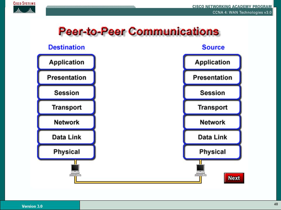
WAN Frame Encapsulation Formats

45
Layer 2 Encapsulation Each WAN connection type uses a Layer 2 protocol to encapsulate traffic while it is crossing the WAN link. To ensure that the correct encapsulation protocol is used, you will need to configure the Layer 2 encapsulation type to use. The choice of encapsulation protocol depends on the WAN technology and the communicating equipment.

47
PPP Common for dialup single-user-to-LAN (dialup and ISDN) or LAN-to-LAN (router-to-router) access. PPP is standardized, so it supports vendor interoperability. It also supports the encapsulation of multiple upper-layer protocols including IP and IPX.

48
HDLC The Cisco default encapsulation type on point-to-point links. It is used typically when communicating with another Cisco device. If communicating with a non-Cisco device, synchronous PPP is a viable option. HDLC is normally proprietary between vendors.

49
LAPB (layer 2 of the X.25 protocol stack)
For packet-switched networks, the LAPB protocol is used to encapsulate X.25 packets. It can also be used over point-to-point links, if the link is unreliable or there is an inherent delay associated with the link, such as in a satellite link. LAPB provides reliability and flow control on a point-to-point basis.

52
HDLC HDLC is Cisco’s default encapsulation for serial lines.
This implementation is very streamlined. There is no windowing or flow control and only point-to-point connections are allowed (no multipoint). 2-byte proprietary type code is inserted after the control field, which means that HDLC framing is not interoperable with other vendors’ equipment.
. 2-byte proprietary type code is inserted after the control field, which means that HDLC framing is not interoperable with other vendors’ equipment.")
54
WAN Design Basics

59
When leased line connections are made:
a router port is required for each connection, along with a CSU/DSU and the actual circuit from the service provider. The cost of dedicated line solutions can become significant when deployed to connect many sites

60
Dedicated connectivity, also referred to as leased lines, provides full- time synchronous connections. Dedicated, full- time connectivity is provided by point-to-point serial links.

62
Network designs tend to follow one of two general design strategies:
mesh hierarchical

63
Mesh structure Net topology is flat All routers perform essentially the same functions Usually no clear definition of where specific functions are performed. Expansion of the network tends to proceed in a haphazard, arbitrary manner.

64
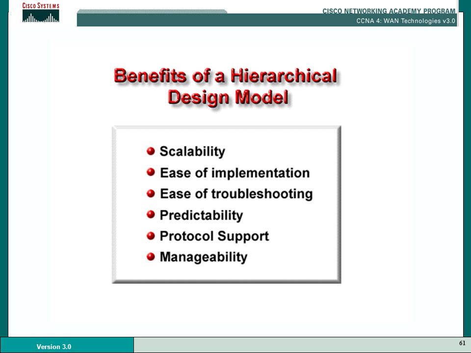
Benefits to using a hierarchical model include the following:
Hierarchical structure the network is organized in layers that each have one or more specific functions. Benefits to using a hierarchical model include the following: Scalability Ease of implementation Ease of troubleshooting Predictability Protocol support Manageability

66
The three-layer model consists of:
core distribution access layers

67
Core layer - Provides fast wide-area connections between geographically remote sites, tying a number of “campus” networks together in a corporate or enterprise WAN. Core links are usually point-to-point, and there are rarely any hosts in the core layer. Core services are typically leased from a telecom service provider (for example, T1/T3, Frame Relay, SMDS, and so on).
.")
68
Distribution layer - Refers to the distribution of network services to multiple LANs within a campus network environment. This layer is where the “campus backbone” network is found, typically based on Fast Ethernet. This layer is implemented on sites that are large and is used to interconnect buildings.

69
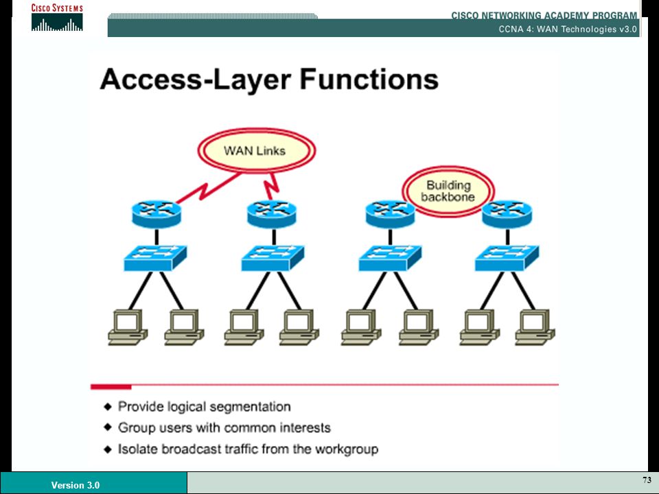
Access layer - Usually a LAN or a group of LANs, typically Ethernet or Token Ring, that provide users with frontline access to network services. The access layer is where almost all hosts are attached to the network, including servers of all kinds and user workstations.

70
The three layers are bounded by Layer 3 devices or other devices that provide separation into broadcast domains. Note: A three-layer model can usually meet the needs of most enterprise networks. However, not all environments require a full three-layer hierarchy—a one- or two-layer design may be adequate. Even in these cases, however, a hierarchical structure should be maintained.

72
The distribution layer would include the campus backbone with all its connecting routers.
Because policy is typically implemented at this level, we can say that the distribution layer provides policy-based connectivity. Policy-based connectivity means that the layer 3 routers are programmed to only allow traffic on the campus backbone that the network manager has determined acceptable.

74
The access layer connects users into LANs, and LANs into campus backbones or WAN links.
This approach enables designers to distribute services across the CPU’s of devices operating at this layer. The access layer allows logical segmentation of the network and the grouping of users based on a function.

76
The one-layer design is typically implemented where:
Only a few remote locations in the company access to applications are mainly done via the local LAN to the site file server. Each site is its own broadcast domain.

78
In a two-layer design, a WAN link is used to interconnect separate sites.
VLANs may be implemented to create separate logical networks without requiring additional routers. Inside the site multiple LANs may be implemented with each LAN segment being its own broadcast domain. Router becomes a concentration point for WAN links.

80
Remote sites can access the WAN core network using WAN technologies other than dedicated links.
Frame Relay or ISDN are two such alternatives. If a remote site is small and has low demand for access to services in the corporate network, ISDN would be a logical choice for this implementation. Perhaps another remote site cannot get access to dedicate WAN links from their service provider but has access to Frame Relay. In either case an entry point needs to be established for these types of WAN connections in to the WAN core.

82
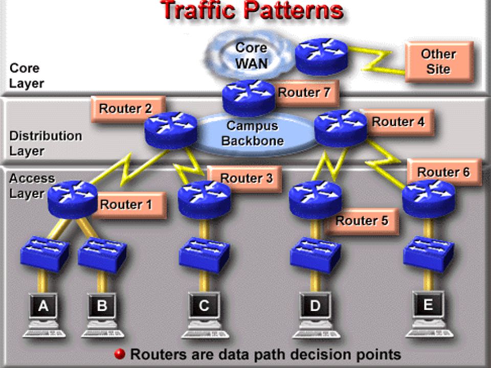
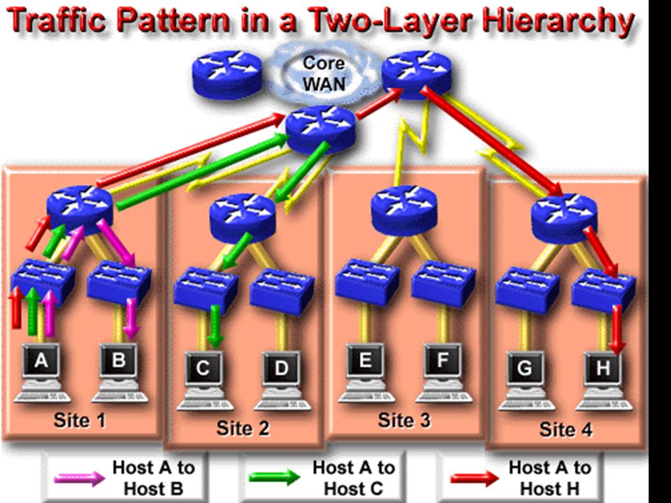
One of the advantages of hierarchical WAN design is it provides a method for controlling data traffic patterns by putting Layer 3 routing points throughout the network. Since routers have the ability to determine paths from the source host to destination hosts based on Layer 3 addressing, data traffic will flow up the hierarchy only as far as it needs to to find the destination host.

84
If Host A were to establish a connection to Host B, the traffic from this connection would travel to Router 1 and be forwarded back down to Host B. Notice that this connection did not require any traffic be placed on the link between Router 1 and Router 2, thus conserving the bandwidth on that link.

86
In a two-layer WAN hierarchy, the traffic patterns are still governed by host source and destination addresses and path determinations of the router. In this model again the traffic will only travel up the hierarchy as far as needed to get to the destination thus conserving bandwidth on other WAN links.

91
Module 2 WAN Technologies

Similar presentations


 is a data communications network that covers a relatively broad geographic area and that.>")
