Download presentation
Presentation is loading. Please wait.

1
Microcontroller Architecture— PIC18F Family
Chapter 2 Microcontroller Architecture— PIC18F Family

2
Harvard Architecture Von Neumann Architecture: Harvard Architecture:
Fetches instructions and data from a single memory space Limits operating bandwidth Harvard Architecture: Uses two separate memory spaces for program instructions and data Improved operating bandwidth Allows for different bus widths Way back in the early days of computer design, two competing architectures came to prominence: The Von Neumann Architecture, sometimes called the Princeton Architecture, and the Harvard Architecture. The Von Neumann Architecture organizes the system such that there is a single memory space and bus for both program instructions and for data. In the beginning of the computer era, memory was the most unreliable and failure prone component of the system. Therefore, the single bus architecture was favored because it simplified the design, improved the reliability of the system and made it easier for technicians to swap out bad memory units. These advantages were a good trade off at the time and offset the disadvantages of the limited operating bandwidth that resulted from the need to fetch multiple bytes from memory just to implement a single instruction. i.e. One fetch to retrieve the instruction and one fetch to retrieve the data associated with that instruction as a minimum. Instructions that required multiple bytes or operated on multiple bytes of data sometimes required several fetches from memory per instruction. Because of the initial popularity of the Von Neumann architecture, most microcontrollers were built around this structure, even though memory had become perhaps the most reliable component of the system. In contrast, the Harvard Architecture has two separate memory spaces: one for program instructions and one for data. This architecture’s primary advantage is in the performance improvement it gains by having two busses that can be active simultaneously. i.e. While fetching an instruction on the program bus, data can be read or written on the data bus. Another advantage is the opportunity to have busses of different widths. Not all Harvard Architecture based microcontrollers take advantage of this, but the PICmicro does. Since the busses are separate, the program bus can be wider than the data bus. Since the PICmicro is an 8-bit microcontroller, the data bus is 8-bits wide. However, because the program bus is separate, it can be optimized to any width that fits within the design goals of the microcontroller. Microchip’s PICmicro family uses three program bus widths: 12-bit, 14-bit and 16-bit which correspond to our base-line (PIC16F5x/PIC12F5xx), mid-range (PIC16Fxxx/PIC12Fxxx), and high end (PIC18) families respectively. The wider busses allow more information to be transferred from memory to the CPU in a single cycle, hence the long word instruction advantage that we will discuss further in subsequent slides.
, mid-range (PIC16Fxxx/PIC12Fxxx), and high end (PIC18) families respectively. The wider busses allow more information to be transferred from memory to the CPU in a single cycle, hence the long word instruction advantage that we will discuss further in subsequent slides.")
3
PIC18F Microcontroller Families
PIC microcontrollers are designed using the Harvard Architecture which includes: Microprocessor unit (MPU) Program memory for instructions Data memory for data I/O ports Support devices such as timers
 Program memory for instructions. Data memory for data. I/O ports. Support devices such as timers.")
4
Microcontroller with the Harvard Architecture

5
PIC18F452/4520 Memory - Example Program Memory: 32 K (215)
Address range: to 007FFFH 16-bit registers Data Memory: 4 K Address range: 000 to FFFH 8-bit registers Data EEPROM Not part of the data memory space Addressed through special function registers

6
PIC18F – MCU and Memory 16 bit 2 MB 221 8 bit 4 KB 212

7
PIC18F – MCU and Memory – Design Problem
Design a micro controller with the following specifications Specify bus widths. Program Memory: 32 K Data Memory: 4 K In your design show where the counter registers are located In your design show where the working registers are located (which part of the microprocessor unit) Show where the read/write lines are connected to – specify the direction of each. 32 K (215)
 Show where the read/write lines are connected to – specify the direction of each. 32 K (215)")
8
PIC18F – MCU and Memory – Design Problem
Design a micro controller with the following specifications Specify bus widths. Program Memory: 32 K (215) Address range: to 007FFFH 16-bit registers Data Memory: 4 K Address range: 000 to FFFH 8-bit registers 32 K (215)
 Address range: to 007FFFH. 16-bit registers. Data Memory: 4 K. Address range: 000 to FFFH. 8-bit registers. 32 K (215)")
9
Microprocessor Unit (1 of 3)
Includes Arithmetic Logic Unit (ALU), Registers, and Control Unit Arithmetic Logic Unit (ALU) WREG – working register Status register that stores flags Instruction decoder – when the instruction is fetched it goes into the ID
, Registers, and Control Unit. Arithmetic Logic Unit (ALU) WREG – working register. Status register that stores flags. Instruction decoder – when the instruction is fetched it goes into the ID.")
10
Microprocessor Unit (2 of 3)
Registers Bank Select Register (BSR) 4-bit register used in direct addressing the data memory File Select Registers (FSRs) 16-bit registers used as memory pointers in indirect addressing data memory Program Counter (PC) 21-bit register that holds the program memory address while executing programs
 4-bit register used in direct addressing the data memory. File Select Registers (FSRs) 16-bit registers used as memory pointers in indirect addressing data memory. Program Counter (PC) 21-bit register that holds the program memory address while executing programs.")
11
Microprocessor Unit (3 of 3)
Control unit Provides timing and control signals to various Read and Write operations

12
PIC18F - Address Buses Address bus
21-bit address bus for program memory addressing capacity: 2 MB of memory 12-bit address bus for data memory addressing capacity: 4 KB of memory

13
Data Bus and Control Signals
16-bit instruction/data bus for program memory 8-bit data bus for data memory Control signals Read and Write

14
Examples Refer to your notes!

15
Instructions inst k movlw k 8-bit Instruction on typical 8-bit MCU
8-bit Program Memory Example: Freescale ‘Load Accumulator A’: 2 Program Memory Locations 2 Instruction Cycles to Execute inst k Limits Bandwidth Increases Memory Size Requirements 1 k 16-bit Program Memory 16-bit Instruction on PIC18 8-bit MCU Because of the separate program memory and data memory spaces employed by the PICmicro, program memory is not restricted to being the same width as data memory. For example, on a Von Neumann architecture device like Freescale’s 8-bit MCU families, the single memory space is 8-bits wide for both data and program instruction storage. Because of this, many instructions will require two bytes of memory to provide all of the information that is required for them to be executed. As an example, the LDAA (Load Accumulator A) instruction, which loads an 8-bit constant into Accumulator A requires one byte for the instruction and one byte for the constant data. This means that in order to execute this instruction, memory must be accessed twice. The inherent inefficiency of this design not only limits throughput, but also complicates planning since it is difficult to determine how much memory will be required to hold a particular number of instructions since some are one, two, three or more bytes long. In stark contrast is the program memory of the PICmicro. Since it is separate from data memory, there is no restriction on its width. At the time that the PIC16 architecture was designed, a 14-bit wide memory was the ideal tradeoff between cost and functionality. The long word instruction allows all the information necessary to execute a particular instruction to be stored in a single program memory location, requiring only a single memory access, thereby offering a throughput and code size advantage over a similar Freescale device. For example, the MOVLW (Move Literal to W) instruction, which is the equivalent to the Freescale LDAA instruction, contains all 8-bits of the constant data within the same memory location as the 6-bit instruction opcode. Since all PIC16 instructions are single word and all but the branch instructions are single cycle, this implies that there will be some code compression ratio between the PICmicro and Von Neumann architecture microcontrollers. In my experience, this ratio ranges from 1.5:1 up to 2:1 depending on the program’s implementation. Example: ‘Move Literal to Working Register’ 1 Program Memory Location 1 Instruction Cycle to Execute movlw k 1 1 1 k k k k k k k k Separate busses allow different widths 2k x 16 is roughly equivalent to 4k x 8
 instruction, which loads an 8-bit constant into Accumulator A requires one byte for the instruction and one byte for the constant data. This means that in order to execute this instruction, memory must be accessed twice. The inherent inefficiency of this design not only limits throughput, but also complicates planning since it is difficult to determine how much memory will be required to hold a particular number of instructions since some are one, two, three or more bytes long. In stark contrast is the program memory of the PICmicro. Since it is separate from data memory, there is no restriction on its width. At the time that the PIC16 architecture was designed, a 14-bit wide memory was the ideal tradeoff between cost and functionality. The long word instruction allows all the information necessary to execute a particular instruction to be stored in a single program memory location, requiring only a single memory access, thereby offering a throughput and code size advantage over a similar Freescale device. For example, the MOVLW (Move Literal to W) instruction, which is the equivalent to the Freescale LDAA instruction, contains all 8-bits of the constant data within the same memory location as the 6-bit instruction opcode. Since all PIC16 instructions are single word and all but the branch instructions are single cycle, this implies that there will be some code compression ratio between the PICmicro and Von Neumann architecture microcontrollers. In my experience, this ratio ranges from 1.5:1 up to 2:1 depending on the program’s implementation. Example: ‘Move Literal to Working Register’ 1 Program Memory Location. 1 Instruction Cycle to Execute. movlw k k. k. k. k. k. k. k. k. Separate busses allow different widths. 2k x 16 is roughly equivalent to 4k x 8.")
17
EEPROM – can be accessed individually
Flash (4K) EEPROM – can be accessed individually 36 I/O ports F FLASH C EPROM 17
 EEPROM – can be accessed individually. 36 I/O ports. F FLASH. C EPROM. 17.")
18
PIC18F452/4520 Memory Program memory with addresses (Flash)
Data memory with addresses Also called Data Register or File Register FFF=212=16x256=4096=4K

19
PIC18F452/4520 – Data Memory with Access Banks
Three ways to access data registers: Direct using Bank Select Registers (BSR) Bank address (4-bit) + Instruction (8-bit) Indirect using File Select Registers (FSR) FSR contains the address of the data register Hence, MPU uses FSR Access Bank using General Purpose Registers (GPR)
 Bank address (4-bit) + Instruction (8-bit) Indirect using File Select Registers (FSR) FSR contains the address of the data register. Hence, MPU uses FSR. Access Bank using General Purpose Registers (GPR)")
20
Data Memory Organization
Access RAM PIC16F8F2520/4520 Register File (data memory) Map 000h 07Fh 256 Bytes Bank 0 GPR Bank 1 GPR Bank 2 Bank 13 Bank 14 Bank 15 GPR Access SFR Access RAM (GPR) 080h 0FFh 100h 1FFh 200h 2FFh D00h DFFh E00h EFFh F00h FFFh F7Fh F80h 00h 7Fh 80h FFh Access Bank GPR=General Purpose Reg. SFR=Special Function Reg. FFF=212=16x256=4096=4K Data Memory up to 4k bytes Data register map - with 12-bit address bus 000-FFF Divided into 256-byte banks There are total of F banks Half of bank 0 and half of bank 15 form a virtual bank that is accessible no matter which bank is selected Before we can discuss how to address data memory locations, we need to understand how data memory is organized. The PIC18 architecture is capable of supporting up to 4k bytes of RAM. Because most instructions are only 16-bits wide (MOVFF being the exception), it is not possible to address data memory in a linear fashion. To get around this limitation, a banking scheme was implemented, breaking down the data memory space into as many as 16 banks of 256 bytes each. There is a special register called the Bank Select Register (BSR for short), which is used to tell the CPU which bank is active. However, there is one additional feature, and that is the Access Bank, which consists of the lower half of bank 0 and upper half of bank 15. These regions may be accessed directly no mater where the BSR is pointing by using the Access bit in all of the byte oriented and bit oriented instructions that we saw earlier. We will see how this works in detail momentarily.
 Map. 000h. 07Fh. 256 Bytes. Bank 0 GPR. Bank 1. GPR. Bank 2. Bank 13. Bank 14. Bank 15 GPR. Access SFR. Access RAM (GPR) 080h. 0FFh. 100h. 1FFh. 200h. 2FFh. D00h. DFFh. E00h. EFFh. F00h. FFFh. F7Fh. F80h. 00h. 7Fh. 80h. FFh. Access Bank. GPR=General Purpose Reg. SFR=Special Function Reg. FFF=212=16x256=4096=4K. Data Memory up to 4k bytes. Data register map - with 12-bit address bus 000-FFF. Divided into 256-byte banks. There are total of F banks. Half of bank 0 and half of bank 15 form a virtual bank that is accessible no matter which bank is selected. Before we can discuss how to address data memory locations, we need to understand how data memory is organized. The PIC18 architecture is capable of supporting up to 4k bytes of RAM. Because most instructions are only 16-bits wide (MOVFF being the exception), it is not possible to address data memory in a linear fashion. To get around this limitation, a banking scheme was implemented, breaking down the data memory space into as many as 16 banks of 256 bytes each. There is a special register called the Bank Select Register (BSR for short), which is used to tell the CPU which bank is active. However, there is one additional feature, and that is the Access Bank, which consists of the lower half of bank 0 and upper half of bank 15. These regions may be accessed directly no mater where the BSR is pointing by using the Access bit in all of the byte oriented and bit oriented instructions that we saw earlier. We will see how this works in detail momentarily.")
21
PIC18F452 I/O Ports Five I/O ports PORT A through PORT E
Most I/O pins are multiplexed Generally have eight I/O pins with a few exceptions Addresses already assigned to these ports in the design stage Each port is identified by its assigned Special Function Registers (SFR) – look at the previous slide PORTA (address of F80) PORTB (address of F81) these are part of data memory or register file TRISB must be set to specify signal direction of PORT B.
 – look at the previous slide. PORTA (address of F80) PORTB (address of F81) these are part of data memory or register file. TRISB must be set to specify signal direction of PORT B.")
22
Processes and Conditions of Data Transfer
Interrupt is a process of communication between two devices If provides efficient communication between the two devices Examples: Sending a file to a printer, pressing a key on the key board External or Internal to the MPU

23
Processes and Conditions of Data Transfer
Parallel data transfer Serial data transfer MPU Initiating Unconditional Conditional (asks if device is ready) RST HW SW
 RST. HW. SW.")
24
Processes and Conditions of Data Transfer
Reset Special type of external interrupt Examples: Manual Reset Power-on Reset Brown-out Reset (power goes below a specifies value)
")
25
MCU Support Devices (1 of 2)
Timers A value is loaded in the register and continue changing at every clock cycle – time can be calculated Can count on rising or falling edge There are several timers: 8-bit, 16-bit Controlled by SFR Master Synchronous Serial Port (MSSP) Serial interface supporting RS232 Addressable USART Another serial data communication A/D converter Parallel Slave Port (PSP) Capture, Compare and PWM (CCP Module) ToCON
 Serial interface supporting RS232. Addressable USART. Another serial data communication. A/D converter. Parallel Slave Port (PSP) Capture, Compare and PWM (CCP Module) ToCON.")
26
PIC18F Special Features Sleep mode Watchdog timer (WDT)
Power-down mode Watchdog timer (WDT) Able to reset the processor if the program is caught in unknown state (e.g., infinite loop) Code protection EEPROM can be protected through SFR In-circuit serial programming In-circuit debugger
 Able to reset the processor if the program is caught in unknown state (e.g., infinite loop) Code protection. EEPROM can be protected through SFR. In-circuit serial programming. In-circuit debugger.")
27
PIC18F4X2 Architecture Block Diagram

28
PIC16F87 Architecture Block Diagram

29
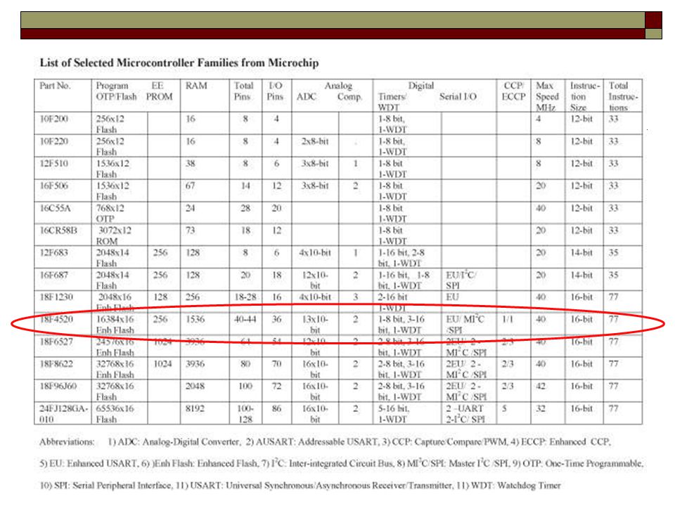
Table 2-1

30
Questions - Table 2-9 (pp. 46 and 48)
How much of flash memory can be accessed? Effective address bus from data memory ? How many instruction sets can PIC16F687 be accessed? 13 bit 8K (1FFF) 9bit 512 Byte 35 – It has no multiplication! – compare Figure 2-8 and 2-9
 9bit 512 Byte. 35 – It has no multiplication! – compare Figure 2-8 and 2-9.")
31
PIC18F Instructions and Assembly Language
Has 77 instructions Earlier PIC family of microcontrollers have either 33 or 35 instructions (Table 2-1) In PIC18F instruction set, all instructions are 16-bit word length except four instructions that are 32-bit length
 In PIC18F instruction set, all instructions are 16-bit word length except four instructions that are 32-bit length.")
32
Instruction Description and Illustrations
Copy (Load) 8-bit number into W register Mnemonics: MOVLW 8-bit Binary format: XXXX XXXX (any 8-bit number) Copy Contents of W register in PORTC Mnemonics: MOVWF PORTC, a (‘a’ indicates that PORTC is in the Access Bank) (82H is PORTC address) Opcode 8-bit Literal 8-bit Instruction
 8-bit number into W register. Mnemonics: MOVLW 8-bit. Binary format: XXXX XXXX (any 8-bit number) Copy Contents of W register in PORTC. Mnemonics: MOVWF PORTC, a. (‘a’ indicates that PORTC is in the Access Bank) (82H is PORTC address) Opcode. 8-bit. Literal. 8-bit. Instruction.")
33
Instruction Set Overview
Literal and Control Operations 15 8 7 Literal Value Opcode k k k k k k k k OR Opcode Literal and control operations encompass everything not covered by the previous two categories. Literal operations are somewhat unique in their implementation within the PICmicro 8-bit families. Unlike other architectures that would use the equivalent of the byte oriented instruction but specify the data preceded by a ‘#’, the PICmicro uses a completely separate instruction. These instructions are characterized by the ending “LW” (such as ADDLW), and all work with constand (hard coded) data as part of their operation, such as adding a literal/constant to the W register. Control operations include instructions like call, goto, and clwdt. These may or may not have any operands depending on their specific function. MOVLW x 25 Literal Value
, and all work with constand (hard coded) data as part of their operation, such as adding a literal/constant to the W register. Control operations include instructions like call, goto, and clwdt. These may or may not have any operands depending on their specific function. MOVLW. x. 25. Literal Value.")
34
Illustration: Displaying a Byte at an I/O Port (1 of 5)
Problem statement: Write instructions to light up alternate LEDs at PORTC. Hardware: PORTC bidirectional (input or output) port; should be setup as output port for display Logic 1 will turn on an LED in Figure 2.10.
 port; should be setup as output port for display. Logic 1 will turn on an LED in Figure")
35
Illustration (2 of 5) Interfacing LEDs to PORTC Port C is F82H
TRISC=0 Interfacing LEDs to PORTC Port C is F82H Note that PORT C is set to be an output! Hence, TRISC (address 94H) has to be set to 0
 has to be set to 0.")
36
Illustration (3 of 5) Program (software)
Logic 0 to TRISC sets up PORTC as an output port Byte 55H turns on alternate LEDs MOVLW 00 ;Load W register with 0 MOVWF TRISC, 0 ;Set up PORTC as output MOVLW 0x55 ;Byte 55H to turn on LEDS MOVWF PORTC,0 ;Turn on LEDs SLEEP ;Power down

37
PIC18 Simulator Using the Program Memory editor type in the opcode MOVLW 00 and MOWWF TRISC,0 as described in page 52 of your textbook. Run the program in step-by-step mode and observe the PC. Observe how the NEXT INSTRUCTION changes. What is the value of final clock cycle? How long does it take to complete the program in sec.?

38
PIC18 Simulator IDE

39
Questions - PIC18 Simulator IDE
What is the address for TRISC? SFR F94 What is the address for PORTE? How many SFR registers we have? FFF-F80 How many GPR? 000-5FF How many bit PC has? Compare with Fig 2-8

40
Example Memory content Hex code Mnemonics Memory content binary code
Leave space

41
Illustration (4 of 5) Execution of the instruction: WREG=55
MOVWF PORTC 1 Copy from WREGPORT C (82H) 2 1 2 Contains 55
 Contains 55.")
Similar presentations


 Ports and Interfacing>")


 are all contained in a single package.>")
