Download presentation
Presentation is loading. Please wait.

1
Chapter 6 Fatigue Failure Theories

2
Fatigue Failure Occurs when stresses are changing throughout the life of a part. _______________________ starts with a crack that propagates until a catastrophic failure occurs. This usually begins at a manufacturing defect or stress concentration that is subjected to tensile stresses for part of its load cycle.

3
Fatigue-Failure Models
Stress-Life - cyclic stresses are kept below fatigue strength or endurance limit. Most widely used. Strain-Life - complicated not often used. _________________ - sometimes used, gaining favor especially in the aircraft and aerospace industry.

5
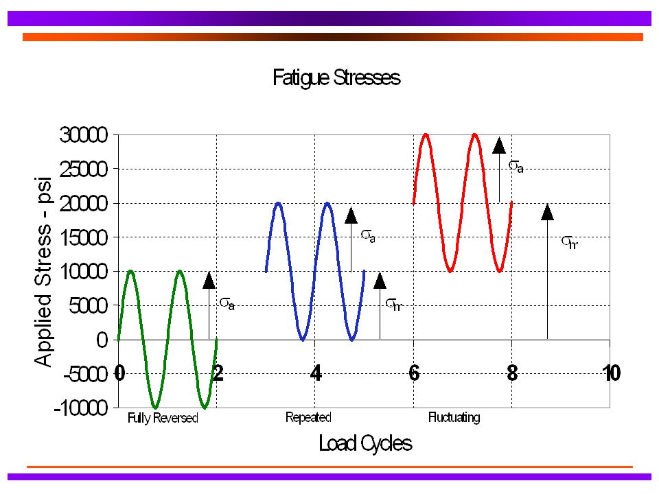
Fully Reversed Failure Criteria
Most data comes from R. R. Moore rotating-beam test. Highly polished specimen of 0.3 inches in diameter is subjected to pure bending stresses that are alternated by rotating the specimen. Rotation is at 1725 rpm. Takes 1/2 day to reach 106 cycles.

7
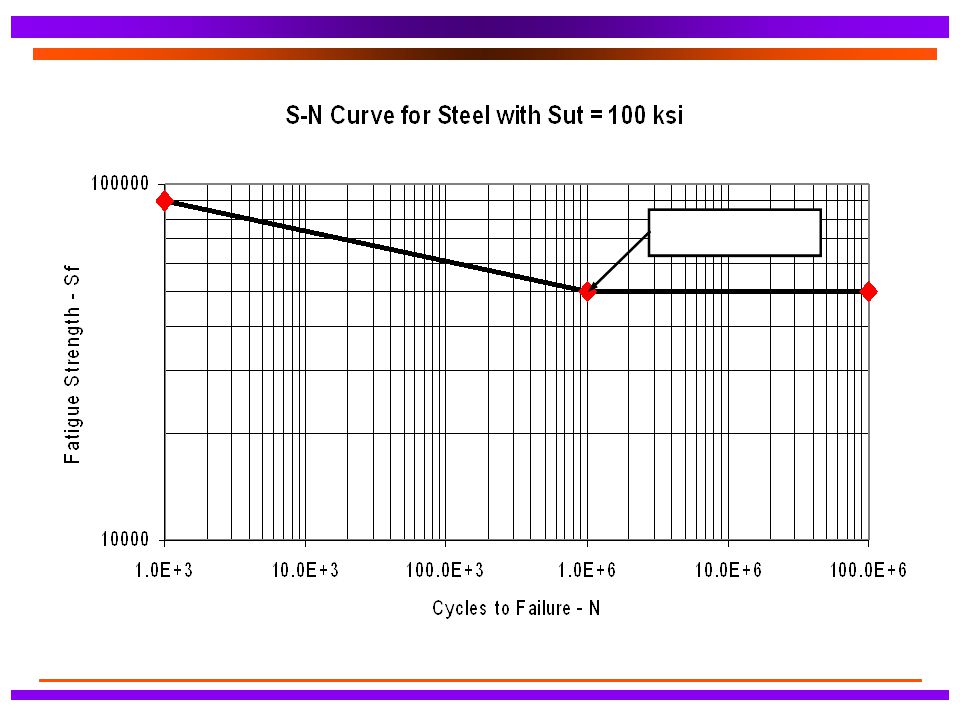
Endurance Limit and Fatigue Strength
Endurance Limit of a Material (Se’) - stress below which fatigue failure does not occur regardless of the number of stress cycles. ____________________Strength of a Material (Sf’) -stress below which fatigue failure does not occur for a specified number of stress cycles.
 - stress below which fatigue failure does not occur regardless of the number of stress cycles. ____________________Strength of a Material (Sf’) -stress below which fatigue failure does not occur for a specified number of stress cycles.")
9
Estimating Se’ or Sf’ For ____________: Se’ = 0.5Sut for Sut<200 ksi (1400 MPa) Se’ = 100 ksi (700 MPa) for Sut>200 ksi (1400 MPa) For ______________: Se’ = 0.4Sut for Sut<60 ksi (400 MPa) Se’ = 24 ksi (160 MPa) for Sut>60 ksi (400 MPa)
 Se’ = 24 ksi (160 MPa) for Sut>60 ksi (400 MPa)")
10
Estimating Se’ or Sf’ cont’d
For __________________: = 0.4Sut for Sut<48 ksi (330 MPa) = 19 ksi (130 MPa) for Sut>330 ksi (330 MPa) For _____________________: Se’ = 0.4Sut for Sut<40 ksi (280 MPa) Se’ = 14 ksi (100 MPa) for Sut>40 ksi (280 MPa)
 = 19 ksi (130 MPa) for Sut>330 ksi (330 MPa) For _____________________: Se’ = 0.4Sut for Sut<40 ksi (280 MPa) Se’ = 14 ksi (100 MPa) for Sut>40 ksi (280 MPa)")
11
Correction Factors to Endurance Limit and Fatigue Strength
Se = CloadCsize CsurfCtempCreliab Se’ Sf = CloadCsize CsurfCtempCreliab Sf’ Se - corrected endurance limit for a part Sf - corrected fatigue strength for a part

12
Correction Factors to Endurance Limit and Fatigue Strength
Cload - load factor see eq. 6.7a pg 348 Csize - size factor see eq’s. 6.7a,b,c pg Csurf - surface factor see Fig’s. 6-26, 6.27, and eq. 6.7e pg

13
Correction Factors to Endurance Limit and Fatigue Strength
Ctemp - temperature factor see eq. 6.7f pg Creliab - reliability factor see Table pg 353

14
Stress Concentration Kf = 1+q(Kt + 1)
Kt - geometric stress concentration factor Kf - ___________________________ q - notch sensitivity factor

16
Modified-Goodman Diagram
Fluctuating Stresses Modified-Goodman Diagram

17
Failure Lines for Fluctuating Stress

18
“Augmented” Modified-Goodman Diagram

19
Stress Concentration Apply Kf to the ______________ components of stress. For __________ materials apply Kt to the mean components of stress.

20
Stress Concentration - cont’d
If Kf|smaxnom| < Sy then: Kfm = Kf If Kf|smaxnom| > Sy then: Kfm = (Sy - Kfsanom)/ |smnom| If Kf|smaxnom - sminnom| < 2Sy then: Kfm = 0
/ |smnom| If Kf|smaxnom - sminnom| < 2Sy then: Kfm = 0.")
21
Factor of Safety for Fluctuating Stress - Case 1

22
Factor of Safety for Fluctuating Stress - Case 2

23
Factor of Safety for Fluctuating Stress - Case 3

24
Factor of Safety for Fluctuating Stress - Case 3

25
Factor of Safety for Fluctuating Stress - Case 4

26
Factor of Safety for Fluctuating Stress - Case 4

27
Multiaxial Stresses in Fatigue
Fluctuating Stresses Multiaxial Stresses in Fatigue

28
Fully Reversed Simple Multiaxial Stresses

29
Fluctuating Simple Multiaxial Stresses
Von Mises Method

30
General Approach to High Cycle Fatigue Design
Generate Modified Goodman Diagram Calculate alternating and mean components of stress at areas of concern on the part. Include appropriate stress concentration factors. Convert alternating and mean applied stresses to alternating and mean Von Mises Stresses. Plot these stresses on the Modified Goodman Diagram and find the factor of safety.

31
Example The figure pertains to the shaft of a disk sander that is made from steel having Su=900 MPa, and Sy=750 MPa. The most severe loading occurs when an object is held near the periphery of the disk with sufficient force to develop 12 N-m (which approaches the stall torque of the motor). Assume a coefficient of friction between the object and the disk is 0.6. What is the factor of safety with respect to eventual fatigue failure of the shaft?
. Assume a coefficient of friction between the object and the disk is 0.6. What is the factor of safety with respect to eventual fatigue failure of the shaft")
32
Example

Similar presentations


 deformation of a material with time under a constant stress. It is both.>")
 analysis (last updated 2011-09-27)>")


