Download presentation
Presentation is loading. Please wait.

1
Chapter 32: Inductance Reading assignment: Chapter 32
Homework 32 (not due, use as practice for exam): OQ1, OQ3, OQ4, OQ5, QQ2, QQ3, QQ4, 1, 4, 6, 9, 16, 17, 32, 40 Joseph Henry ( ) Previous chapters: A current creates a magnetic field An emf and a current are induced in a wire loop when the magnetic flux through the loop changes. Now: Self-inductance, inductance, inductor – a circuit element Energy in an inductor RL Mutual inductance RC, RLC circuits Distinguish between emfs and currents caused by batteries, and those induced by changing magnetic fields.
: OQ1, OQ3, OQ4, OQ5, QQ2, QQ3, QQ4, 1, 4, 6, 9, 16, 17, 32, 40. Joseph Henry ( ) Previous chapters: A current creates a magnetic field. An emf and a current are induced in a wire loop when the magnetic flux through the loop changes. Now: Self-inductance, inductance, inductor – a circuit element. Energy in an inductor. RL. Mutual inductance. RC, RLC circuits. Distinguish between emfs and currents caused by batteries, and those induced by changing magnetic fields.")
2
Final exam: Tuesday, Dec. 9, 9:00 am -12:00 pm (room TBA), Thursday, Dec. 11, 9:00 am -12:00 pm (room TBA), Saturday, Dec. 13, 9:00 am -12:00 pm (Olin 101) Comprehensive, chapters 23 – 32 (as far as we got, slide 19 (mutual inductance) Same format as midterms 1 and 2. Equation sheet will be provided Review session, Wednesday, Dec. 10, 5:00 pm – 6:00 pm Use homework 32 for practice for exam
 Comprehensive, chapters 23 – 32 (as far as we got, slide 19 (mutual inductance) Same format as midterms 1 and 2. Equation sheet will be provided. Review session, Wednesday, Dec. 10, 5:00 pm – 6:00 pm. Use homework 32 for practice for exam.")
3
Self Inductance A Self-induced emf: l E L= 𝑁∙ 𝛷 𝐵 𝐼
Consider a solenoid L, connect it to a battery What happens as you close the switch? Lenz’s law – loop resists change in magnetic field Magnetic field is caused by the original current “Inductor” resists change in current A l + – E Self-induced emf: L= 𝑁∙ 𝛷 𝐵 𝐼 L is the inductance of coil It is a measure of how much the inductor (coil) will resist a change in current L is measured in Henry (1 H).
 will resist a change in current. L is measured in Henry (1 H).")
4
A White board example l E
Inductance of a solenoid Consider a long, uniformly wound solenoid, having N turns, length, l, and cross-sectional area A. Find the inductance, L, of the solenoid. Calculate L for 300 turns, l = 0.25 m and cross-sectional area A = 4 cm2. E + – A l L depends on geometry and N

5
Inductors L An inductor in a circuit is denoted by this symbol:
An inductor satisfies the formula: 𝜀=−𝐿 𝑑𝐼 𝑑𝑡 L is the inductance Measured in Henrys (H); 1H = 1V·s/A
; 1H = 1V·s/A.")
6
Kirchhoff's rules for Inductors
Assign currents to every path, as usual Kirchhoff's first law is unchanged The voltage change for an inductor is 𝐿 𝑑𝐼 𝑑𝑡 Negative if with the current Positive if against the current In steady state (dI/dt = 0), an inductor is a wire I + – L E What is Kirchhoff's law for the loop above when the switch is closed? A) E + L (dI /dt) = 0 B) E – L (dI /dt) = 0 C) None of the above D) I don’t know Kirchhoff's law for switches
, an inductor is a wire. I. + – L. E. What is Kirchhoff s law for the loop above when the switch is closed A) E + L (dI /dt) = 0 B) E – L (dI /dt) = 0. C) None of the above D) I don’t know Kirchhoff s law for switches.")
7
White board example The current in a 90.0 mH inductor changes with time as I = t2 - 6t (in SI units). Find the magnitude of the induced emf at (a) t = 1.00 s and (b) t = 4.00 s. (c) At what time is the emf zero.
 t = 1.00 s and. (b) t = 4.00 s. (c) At what time is the emf zero.")
8
An inductor slows down a change in current.
RL Circuits S1 L E + – R 𝐼= 𝜀 𝑅 1− 𝑒 −𝑡/𝜏 Derive on board 𝜏= 𝐿 𝑅 An inductor slows down a change in current.

9
RL Circuits L E + – R b 𝐼= 𝜀 𝑅 𝑒 −𝑡/𝜏 = 𝐼 0 𝑒 −𝑡/𝜏 𝜏= 𝐿 𝑅

10
White board example. The circuit elements have the following values e = 12.0 V, R = 6.00 W, L = 30.0 mH. Find the time constant of the circuit. If S1 is closed, and S2 is in position a, at what time will the current have reached 90% of its maximum value? Switch S2 is at position a, and switch S1 is thrown closed at t = 0. Calculate the current in the circuit at t = 2 ms. Compare the potential difference across the resistor with that across the inductor. L E + – R

11
i-clicker. When the switch is closed, the current through the circuit exponentially approaches a value 𝐼= 𝜀 𝑅 . If we repeat this experiment with an inductor (e.g. solenoid) that has twice the number of turns per unit length, the time it takes for the current to reach a value of I/2 A increases. B. decreases. C. is the same.
 that has twice the number of turns per unit length, the time it takes for the current to reach a value of I/2. A increases. B. decreases. C. is the same.")
12
Loop has unin-tended inductance
Concept Question The circuit at right is in a steady state. What will the voltmeter read as soon as the switch is opened? R1 = 10 L I = 1 A V R2 = 1 k + – E = 10 V The current remains constant at 1 A It must pass through resistor R2 The voltage is given by V = IR RL circuit RLC circuit Tesla coil Spark Two coils Transformer Note that inductors can produce very high voltages Inductance causes sparks to jump when you turn a switch off + – Loop has unin-tended inductance

13
i-clicker. When the switch in the circuit below is closed, the brightness of the bulb Starts off at its brightest and then dims. Slowly reaches its maximum brightness. Immediately reaches it maximum, constant brightness. Something else. (Assume the inductor has no resistance.)
")
14
Energy in Inductors Is the battery doing work on the inductor? L E
+ – L E Is the battery doing work on the inductor? Integral of power is work done on the inductor It makes sense to say there is no energy in inductor with no current Energy density inside a solenoid? Just like with electric fields, we can associate the energy with the magnetic fields, not the current carrying wires

15
Inductors in series and parallel
For inductors in series, the inductors have the same current Their EMF’s add: L1 For inductors in parallel, the inductors have the same EMF but different currents L2

16
Parallel and Series - Formulas
Capacitor Resistor Inductor Series Parallel Fundamental Formula

17
Mutual Inductance Consider two solenoids sharing the same volume
What happens as you close the switch? Current flows in one coil But Lenz’s Law wants mag. flux constant Compensating current flows in other coil Allows you to transfer power without circuits being actually connected It works even better if source is AC from generator + – E I1 I2 The name “Mutual Inductance” is termed due to the fact that it involves interaction of two circuits. Depends on geometry of both circuits and orientations. Mutual Inductance of coil 2 w/r to coil 1 depends on flux by coil 1 through coil 2.

18
Not enough information.
i-clicker. The centers of two coils are moved closer together without changing their relative orientation. What happens to the mutual induction of the two coils? It increases It decreases It stays the same Not enough information. Explain. M = N*Phi/I, ability to have flux for given amount of current. + – E I1 I2

19
E IA IB White board example.
Two solenoids A and B, spaced close to each other and sharing the same cylindrical axis, have 400 and 700 turns, respectively. A current of 3.5 A in solenoid A produces an average flux of 300 µWb through each turn of A and a flux of 90.0 µWb through each turn of B. Calculate the mutual inductance of the two solenoids. What is the inductance of solenoid A? What emf is induced in B when the current in A changes at the rate of A/s? E + – IA IB

20
White board example. On a printed circuit board, a relatively long straight conductor and a conducting rectangular loop lie in the same plane, as shown below. If h = mm, w = 1.30 mm, and L = 2.70 mm, what is their mutual inductance?

21
i-clicker. The primary coil of a transformer is connected to a battery, a resistor, and a switch. The secondary coil is connected to an ammeter. When the switch is thrown closed, the ammeter shows zero current. a nonzero current for a short instant. a steady current. Something else.

22
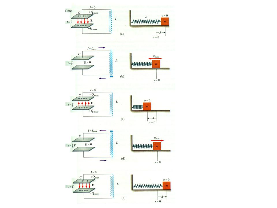
LC Circuits Inductor (L) and Capacitor (C)
Let the battery charge up the capacitor Now flip the switch Current flows from capacitor through inductor Kirchoff’s Loop law gives: Extra equation for capacitors: I Q C + – E L Ch 28 for I, Add minus sign if I doesn’t enter from the same side as +Q What function, when you take two deriva-tives, gives the same things with a minus sign? This problem is identical to harmonic oscillator problem

23
Energy sloshes back and forth
LC Circuits (2) Substitute it in, see if it works I Q C L Let’s find the energy in the capacitor and the inductor Energy sloshes back and forth
 Substitute it in, see if it works. I. Q. C. L. Let’s find the energy in the capacitor and the inductor. Energy sloshes back and forth.")
26
Frequencies and Angular Frequencies
The quantity is called the angular frequency The period is the time T you have to wait for it to repeat The frequency f is how many times per second it repeats T WFDD broadcasts at 88.5 FM, that is, at a frequency of 88.5 MHz. If they generate this with an inductor with L = 1.00 H, what capacitance should they use?

27
White board example. A 1.00 µF capacitor is charged by a 40 V power supply. The fully-charged capacitor is then discharged through a 10.0 mH inductor. Find the maximum current in the resulting oscillations.

28
RLC Circuits Resistor (R), Inductor (L), and Capacitor (C)
Let the battery charge up the capacitor Now flip the switch Current flows from capacitor through inductor Kirchoff’s Loop law gives: Extra equation for capacitors: I Q C + – E L R This equation is hard to solve, but not impossible It is identical to damped, harmonic oscillator

Similar presentations