Download presentation
Presentation is loading. Please wait.

1
ECIV 720 A Advanced Structural Mechanics and Analysis Solid Modeling

2
Summary of Procedure T Nodes should be placed at Discretize domain - start & end of distributed loads - point loads

3
Summary of Procedure For Every Element Compute Strain-Displacement Matrix B 1 2 3 q6q6 q5q5 q4q4 q3q3 q2q2 q1q1 v u

4
Summary of Procedure Element Stiffness Matrix Node Equivalent Body Force Vector Node Equivalent Traction Vector

5
Summary of Procedure Collect ALL Point Loads in Nodal Load Vector 1 N P x1 P y1 P xN P yN

6
Summary of Procedure Form Stiffness Equations

7
Summary of Procedure Apply Boundary Conditions Solve For Every Element Compute Stress

8
Modeling Issues Data Preparation The three modes of typical FE software Pre-Processing Processing Post-Processing Solid Modeling Meshing Solution Convergence

9
Data Processing For a given physical problem select an appropriate mathematical model e.g. Plane Stress Beam

10
Set Up General Model Data MaterialProperties NoNameEv …. idBananaxxx SectionProperties NoNameAIx yy …. idApplexxx ConstantsProperties NoNameP1P2 PP …. idOrangexxx

11
Set Up General Model Data Element GroupsOptionsProperties NoTypeMatSecThk 11D AxialTensionid n/a 21D Axialid n/a 32D CSTPlane stressid 42D CSTPlane strainid n/a

12
Finite Element Mesh May be Defined in Direct Way Solid Modeling approach Nodes Elements Loads BC Geometry of Solid Loads BC Automatic Mesh Generation

13
Direct FEM Mesh Manually define nodes, elements, BC & loads

14
Direct FEM Mesh Typical Input Data (Text File or GUI) Actual depends on software
 Actual depends on software")
15
Direct FEM Mesh

16
Solid Modeling Describe Geometry of FE Domain as a collection of Primitive Entities Point Line Surface Volume

17
Solid Modeling Point Do not confuse with FEM node Line Any two points define a line Points belong to line

18
Solid Modeling Surface Any closed loop of lines define surface Points belong to lines Points AND lines belong to surface 2 faces are defined

19
Solid Modeling Volume Any closed loop of faces defines volume Points belong to lines Points AND lines belong to surface Points AND lines AND Surfaces belong to volume

20
Solid Modeling Boolean Operations Primitive Entities can be used to form more complex solid geometries

21
Solid Modeling Boolean Operations

22
Solid Modeling Each of the primitive or the derived entities (objects) is assigned a set of properties such as material, FEM type, etc. Typically, derived objects inherit properties of parents. At any point, such properties can be changed

23
Solid Modeling Loads and Boundary Conditions can now be applied on primitive objects regardless of the specific Finite Elements.

24
Automatic Meshing Structured Mesh (Mapped) Free Mesh Based on Geometric Transformations Triangulation Techniques Solid Model
 Free Mesh Based on Geometric Transformations Triangulation Techniques Solid Model")
25
Structured Mesh Transformation Through Shape Functions Map to Parent

26
Structured Mesh

27
Free Mesh Triangulation Technique Suitable for arbitrary geometries

28
Example Using ANSYS thickness=1” 10” 5” Plane Stress With Thickness E=29x10 6

29
Define Element Groups

30
Define Element Options

31
Define Thickness

32
Define Material

33
Define Key points

34
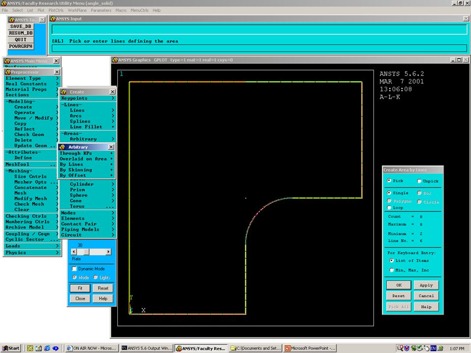
Defining Areas

35
Deleting Entities

36
Automatic Meshing - Coarse

37
Applying Boundary Conditions

38
Applying Loads

39
Positive Value Towards line

40
Processing…

41
Deformed Shape

42
Vertical Displacement

43
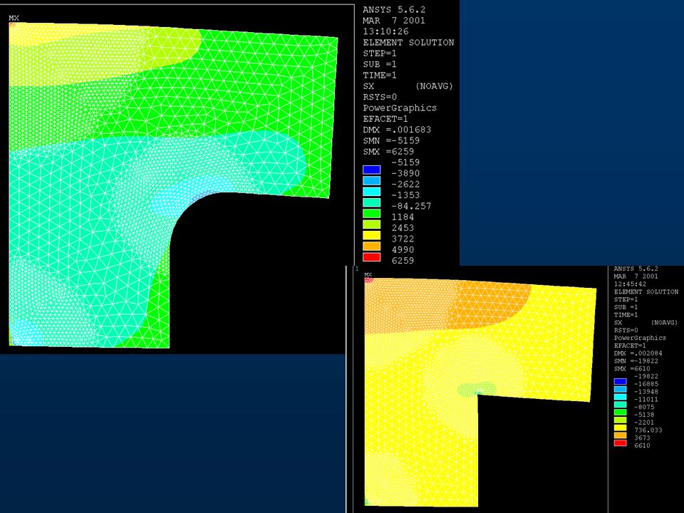
xx

44
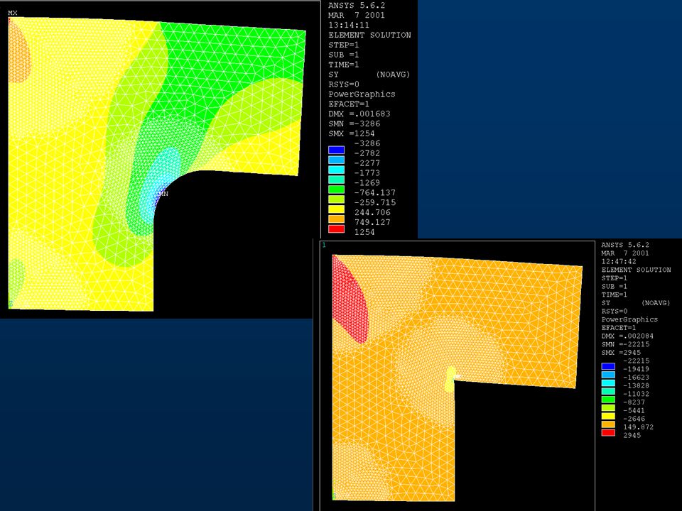
yy

45
Medium Mesh

46
Vertical Displacement Uy = 0.002042 in Compare to Uy = 0.001905 in

47
x & y

48
Refine Mesh

49
Refined Mesh

50
Displacement Uy

51
x & y

52
Very Fine Mesh With Element Refinement

53
Vertical Displacement Compare to Uy = 0.002042 in Uy = 0.001905 in Uy = 0.002084 in

54
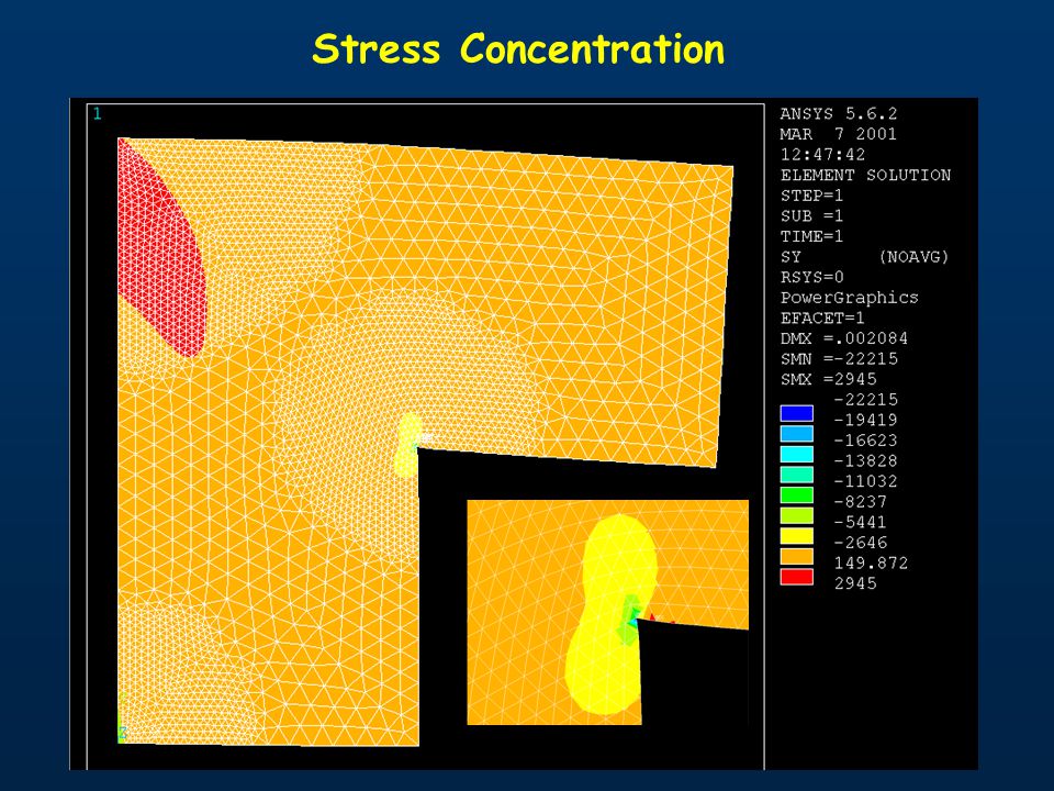
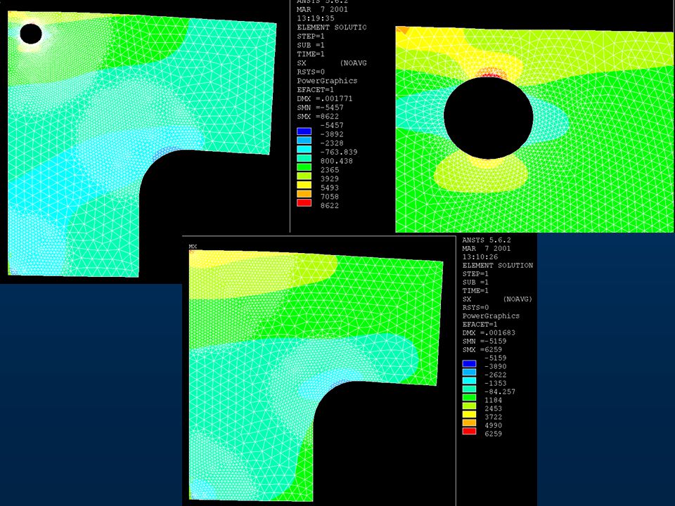
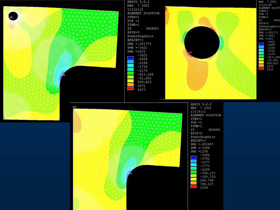
Stress Concentration

56
xx

57
yy

64
COMMON MISTAKES Material properties are zero in elements that share a node One or more structure nodes are not connected to an element One or more parts of the structure are not connected to the remainder Unspecified or inadequate boundary conditions Data Input

65
COMMON MISTAKES A spurious mode (mechanism) is possible because of inadequate connections Too many releases prescribed at a joint Large stiffness differences Part of the structure has buckled In nonlinear analysis, supports or connections have reached zero stiffness (part of structure inadequatly supported) Data Input
 is possible because of inadequate connections Too many releases prescribed at a joint Large stiffness differences Part of the structure has buckled In nonlinear analysis, supports or connections have reached zero stiffness (part of structure inadequatly supported) Data Input")
66
COMMON MISTAKES Elements are of the wrong type (shell elements used where solid elements required) Mesh is too coarse or element capability too limited Loads are wrong in location, type or direction Boundary conditions are wrong in location type or direction Decimal points misplaced or mixed units used Results appear correct
 Mesh is too coarse or element capability too limited Loads are wrong in location, type or direction Boundary conditions are wrong in location type or direction Decimal points misplaced or mixed units used Results appear correct")
67
COMMON MISTAKES Element may be defined twice Results appear correct

Similar presentations


Mechanics of Materials Approach (A) Complex Beam Theory (i) Straight Beam (ii) Curved Beam (iii)>")


