Download presentation
Presentation is loading. Please wait.

1
Rigid Pavement Design Course Crack Pattern Development

2
Rigid Pavement Design Course CRC Pavement Vetter, C.P. 1933 Reinforced Concrete Drying Shrinkage Temperature Drop Consider a unit Length (L) between cracks a. is restrained by the reinforcement b. Causes tension in concrete & compression in the steel. c. Bond stress between steel & concrete and the concrete & subgrade
 between cracks a. is restrained by the reinforcement b. Causes tension in concrete & compression in the steel. c. Bond stress between steel & concrete and the concrete & subgrade.")
3
Rigid Pavement Design Course (1)Bond stress in the vicinity of crack (2)Compression in steel and tension in the concrete increases until steel = concrete. In this region there is no bond slip or stress. d. Subsequent crack form in concrete when bond stress exceeds the concrete tensile strength.

4
Rigid Pavement Design Course Free Edge ‘t’ L Longitudinal Joint Traverse Crack C L

5
Rigid Pavement Design Course Crack AsfsAsfs A s f sc AcftAcft Section XX Section YY Forces Acting on CRC Pavement Section Probable Strain Distribution Adjacent to a Crack

6
Rigid Pavement Design Course Extensive bond slip Crack L/2=nS min Good bond

7
Rigid Pavement Design Course Unrestrained shrinkage strain Concrete strain Crack width: equation 2.10a Steel strain S min or (L-2x)/2 Compression Tension Strain Crack width: equation 2.10b
/2 Compression Tension Strain Crack width: equation 2.10b")
8
Rigid Pavement Design Course Concrete Stress Steel stress Stressed, full restraint c.g. of bond h b/2 c Condition of no stress L cw Stresses and Strains in Fully Restrained, Cracked Reinforced Concrete for Decreasing Temperature

9
Rigid Pavement Design Course Assumptions of Vetter Analysis 1.Volumetric ‘s are uniformly distributed. 2. Compatibility exists in bonded region. 3.Total bond force= Total Tensile Force= Total change in the steel stress 4.Total length of steel will remain unchanged. Total elongation = Total shortening 5.Equilibrium exists between forces at crack & the forces in the fully bonded region. In partially bonded region; compatibility of deformation does not exist. Crack width results from relative displacement between the steel and the concrete.

10
Rigid Pavement Design Course Stress Distribution Between Cracks Subject to Shrinkage L C of Crack u x L Bond Stress Tension b) Concrete Stresses a) Steel Stresses Compression Tension x1x1 f tz f sz c) Bond Stresses
 Concrete Stresses a) Steel Stresses Compression Tension x1x1 f tz f sz c) Bond Stresses")
11
Rigid Pavement Design Course (1) Center of crack spacing (2) Bond Force = Concrete tensile force = Change in steel force (3) Total length of steel bars remain unchanged total shortening= total elongation
 Center of crack spacing (2) Bond Force = Concrete tensile force = Change in steel force (3) Total length of steel bars remain unchanged total shortening= total elongation")
12
Rigid Pavement Design Course Total Shortening = Total Elongation Note

13
Rigid Pavement Design Course For temp. drop Both

14
Rigid Pavement Design Course a) Steel Stresses b) Concrete Stresses Bond Stress y L c) Bond Stresses u Tension C of Crack L Stress Distribution Between Cracks Subject to Temperature Drop
 Steel Stresses b) Concrete Stresses Bond Stress y L c) Bond Stresses u Tension C of Crack L Stress Distribution Between Cracks Subject to Temperature Drop")
15
Rigid Pavement Design Course (1) Center of crack spacing (2) Bond Force = concrete tensile force = change in steel force (3) Total length of steel bars remain unchanged total shortening= total elongation
 Center of crack spacing (2) Bond Force = concrete tensile force = change in steel force (3) Total length of steel bars remain unchanged total shortening= total elongation")
16
Rigid Pavement Design Course For temp. drop Both

17
Rigid Pavement Design Course Average Crack Spacing (ft) Ratio of Steel bond Area to Concrete Volume x 10 -2 (in. 2 /in. 3 ) Relationship Between Steel Bond Area and Crack Spacing 2 3 4 5 6 7 20 18 16 12 8 4 0 Pavements Placed During Winter = Summer =
 Relationship Between Steel Bond Area and Crack Spacing Pavements Placed During Winter = Summer =.")
18
Rigid Pavement Design Course Development Length Allowable Bond Stress Design Strength of the Bar ACI Definition of Development Length (a) Assumed and Actual Bond Stress-Slip Relationships.
 Assumed and Actual Bond Stress-Slip Relationships.")
19
Rigid Pavement Design Course Actual Bond Stress Development Length Vetter Allowable Bond Stress Force in Bar Under Working Stress Condition Stress Transfer Length (b)
")
20
Rigid Pavement Design Course Bond Stress Relative Slip Between Concrete and Steel As Modeled in Computer Program Actual bond Stress-Slip Relationship (c)
")
21
Rigid Pavement Design Course concrete tension specimen steel bar P (a) (b) (c) ab x SbSb x-Displ. Slip Determination of Slip from Strain Functions ACI

22
Rigid Pavement Design Course

23

24
Relative to temperature drop Max. drop to cause L = 2x substitute for in equation For a greater temp. drop t 2 ……only if otherwise

25
Rigid Pavement Design Course

27
Structural Response Models Uniform Bond Stress Distribution Vetter: Shrinkage and Temperature Drop Zuk: Shrinkage Friberg: Temperature Drop

28
Rigid Pavement Design Course Hughes: Shrinkage and temperature Drop (concrete only)
")
29
Rigid Pavement Design Course CRCP-2: Computer Model for Shrinkage and Temperature Drop (force equilbrium) Regression Equations:
 Regression Equations:")
30
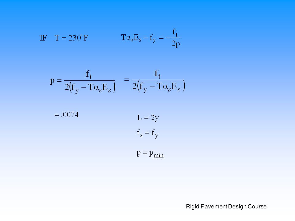
Rigid Pavement Design Course Percent Steel (p) ; prevent yielding ; p=p min f s =f y u L x Um Non-Uniform Bond Stress Distribution TTICRCP: Computer model for Shrinkage and Temperature Drop (force equilibrium and energy balance) Reis: Shrinkage and Temperature Drop
 ; prevent yielding ; p=p min f s =f y u L x Um Non-Uniform Bond Stress Distribution TTICRCP: Computer model for Shrinkage and Temperature Drop (force equilibrium and energy balance) Reis: Shrinkage and Temperature Drop")
31
Rigid Pavement Design Course 2002 AASHTO Guide CRC Design K1K1 K2K2

32
Rigid Pavement Design Course Crack Width

33
Rigid Pavement Design Course Crack Spacing Distribution vc. spc %P

Similar presentations