Download presentation
Presentation is loading. Please wait.

1
Module 7 Hardware

2
Introduction Switches are the basic blocks of computer hardware. We build increasingly complex hardware from these simple switches. An example of a switch that we use everyday in our lives is the Light Switch.

3
Introduction The switches that we use in computer hardware are far too small to be seen by the naked eye. Then how are these components constructed if they are that small?

4
Introduction The answer rests in three technologies:

5
Introduction The answer rests in three technologies: – The idea of representing information by electrical signals which led to development of the telegraph. Switching devices developed such as Vacuum tubes, but they all suffered from the disadvantages of being large, high power consumption and slow speed.

6
Introduction The answer rests in three technologies: – The idea of representing information by electrical signals which led to development of the telegraph. Switching devices developed such as Vacuum tubes, but they all suffered from the disadvantages of being large, high power consumption and slow speed. – Invention of transistor which is a very small switch.

7
Introduction The answer rests in three technologies: – The idea of representing information by electrical signals which led to development of the telegraph. Switching devices developed such as Vacuum tubes, but they all suffered from the disadvantages of being large, high power consumption and slow speed. – Invention of transistor which is a very small switch. – Photography. The computer scientists got the idea of having layers of chemicals on top of each other from photography to “print” the wires of circuit directly on a non-conducting base and this led to invention of Integrated Circuits (ICs) which packs thousands of transistors on one chip.
 which packs thousands of transistors on one chip..")
8
Electrical Switches We adopt the convention that:

9
Electrical Switches We adopt the convention that: – A high voltage in a wire is represented by the symbol 1. – Little or no voltage in a wire represented by symbol 0.

10
Electrical Switches We adopt the convention that: – A high voltage in a wire is represented by the symbol 1. – Little or no voltage in a wire represented by symbol 0. With this convention a switch can be viewed as a logic operator.

11
Electrical Switches We adopt the convention that: – A high voltage in a wire is represented by the symbol 1. – Little or no voltage in a wire represented by symbol 0. With this convention a switch can be viewed as a logic operator. Think of a switch as box with three wires connected to it called in, out and control.

12
Electrical Switches We adopt the convention that: – A high voltage in a wire is represented by the symbol 1. – Little or no voltage in a wire represented by symbol 0. With this convention a switch can be viewed as a logic operator. Think of a switch as box with three wires connected to it called in, out and control. Our switches will come in two basic varieties:

13
Electrical Switches We adopt the convention that: – A high voltage in a wire is represented by the symbol 1. – Little or no voltage in a wire represented by symbol 0. With this convention a switch can be viewed as a logic operator. Think of a switch as box with three wires connected to it called in, out and control. Our switches will come in two basic varieties: – Normally open – Normally closed

14
An electronic switch in general

15
Normally Open Switch In a normally open switch, current can pass from in to out only when there is a signal at the control wire.

16
Normally Open Switch In a normally open switch, current can pass from in to out only when there is a signal at the control wire. That is when control is 1.

17
Normally Open Switch In a normally open switch, current can pass from in to out only when there is a signal at the control wire. That is when control is 1. Otherwise the value of out is 0.

18
Normally Open Switch

19
Normally Closed Switch In a normally close switch, current can pass from in to out unless there is a signal at the control wire.

20
Normally Closed Switch In a normally close switch, current can pass from in to out unless there is a signal at the control wire. That is when control is 0.

21
Normally Closed Switch In a normally close switch, current can pass from in to out unless there is a signal at the control wire. That is when control is 0. Otherwise the value of out is 0.

22
Normally Closed Switch

23
Logic From computer science perspective we are not concerned with electrical currents and voltages.

24
Logic From computer science perspective we are not concerned with electrical currents and voltages. We adopted the convention that:

25
Logic From computer science perspective we are not concerned with electrical currents and voltages. We adopted the convention that: – A high voltage in a wire is represented by the symbol 1. – Little or no voltage in a wire represented by symbol 0.

26
Logic From computer science perspective we are not concerned with electrical currents and voltages. We adopted the convention that: – A high voltage in a wire is represented by the symbol 1. – Little or no voltage in a wire represented by symbol 0. With this convention a switch can be viewed as a logic operator.

27
Logic From computer science perspective we are not concerned with electrical currents and voltages. We adopted the convention that: – A high voltage in a wire is represented by the symbol 1. – Little or no voltage in a wire represented by symbol 0. With this convention a switch can be viewed as a logic operator. We can regard a switch as an operator that produces an output state depending only on the input states.

28
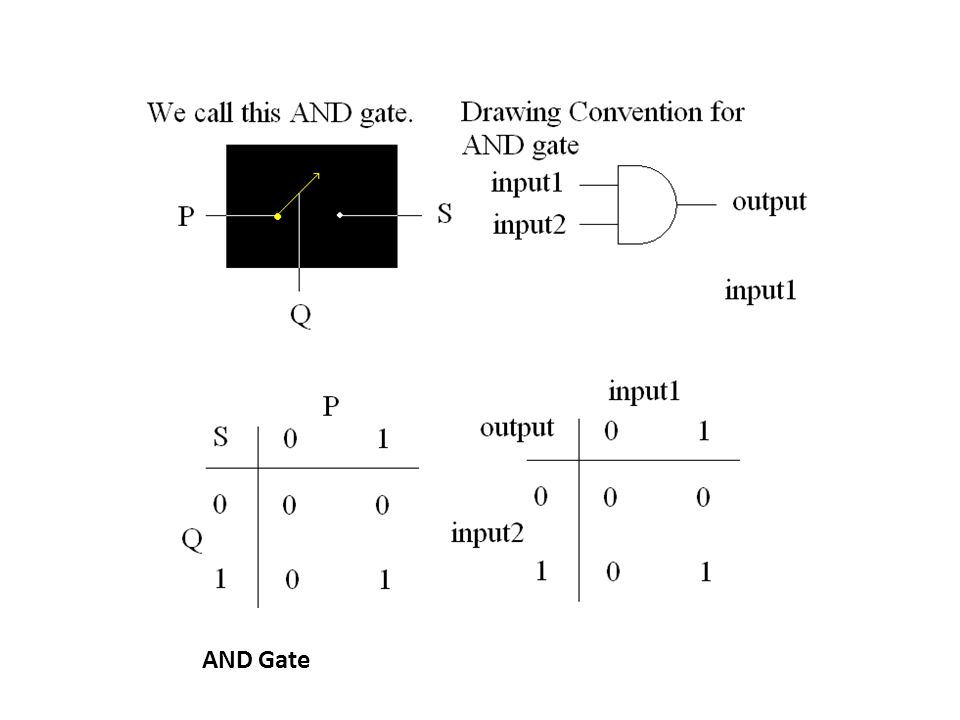
Logic Example: S = John and Merry are happy. P = John is happy. Q = Merry is happy. S = P AND Q.

29
Logic Example: S = John and Merry are happy. P = John is happy. Q = Merry is happy. S = P AND Q. AND is a logical operator. We refer to P and Q as components of logical operator AND.

30
Logic Suppose we decide to interpret – 0 as false. – 1 as true.

31
Logic Suppose we decide to interpret – 0 as false. – 1 as true. Then the action of normally open switch is the same, under this interpretation, as that of AND logical operator.

32
Logic Suppose we decide to interpret – 0 as false. – 1 as true. Then the action of normally open switch is the same, under this interpretation, as that of AND logical operator. Logical AND operator is evaluated to true if and only if both of its operands are true.

33
Logic

34
A normally open switch acts as an AND operator. We refer to it as an AND gate. It has three components: – two input lines. – one output line. AND Gate

36
OR gate OR is another logical operator. We also have a gate for OR and we call it OR gate.

37
OR gate OR is another logical operator. We also have a gate for OR and we call it OR gate. An OR gate like AND gate has three components: – Two input lines – One output line

38
OR gate OR is another logical operator. We also have a gate for OR and we call it OR gate. An OR gate like AND gate has three components: – Two input lines – One output line A Logical OR operator evaluates as true if at least one of the operands are true.

39
OR gate OR is another logical operator. We also have a gate for OR and we call it OR gate. An OR gate like AND gate has three components: – Two input lines – One output line A Logical OR operator evaluates as true if at least one of the operands are true. In the same line, an OR gate has output 1 if at least one of the input lines are 1.

40
OR Gate

41
NOT Gate We have logical operator NOT which reverses the truth value of its statement. Ex: R = Peter is happy. then, NOT R = Peter is not happy.

42
NOT Gate We have logical operator NOT which reverses the truth value of its statement. Ex: R = Peter is happy. then, NOT R = Peter is not happy. As two other logical operator we have a corresponding NOT gate which has two components: – One input line – One output line

43
NOT gate

44
Logical Expressions We can use the three basic logical operators, AND, NOT and OR to build any logical expression by combining them. EX: We have two named statements: P = Button A has been pushed. R = Button B has been pushed. We want to write an expression Q which is true when either both of the buttons have been pushed or none of them.

45
Example PRQ 111 100 010 001 True = 1 False = 0 P = 1 means button A has been pushed.

46
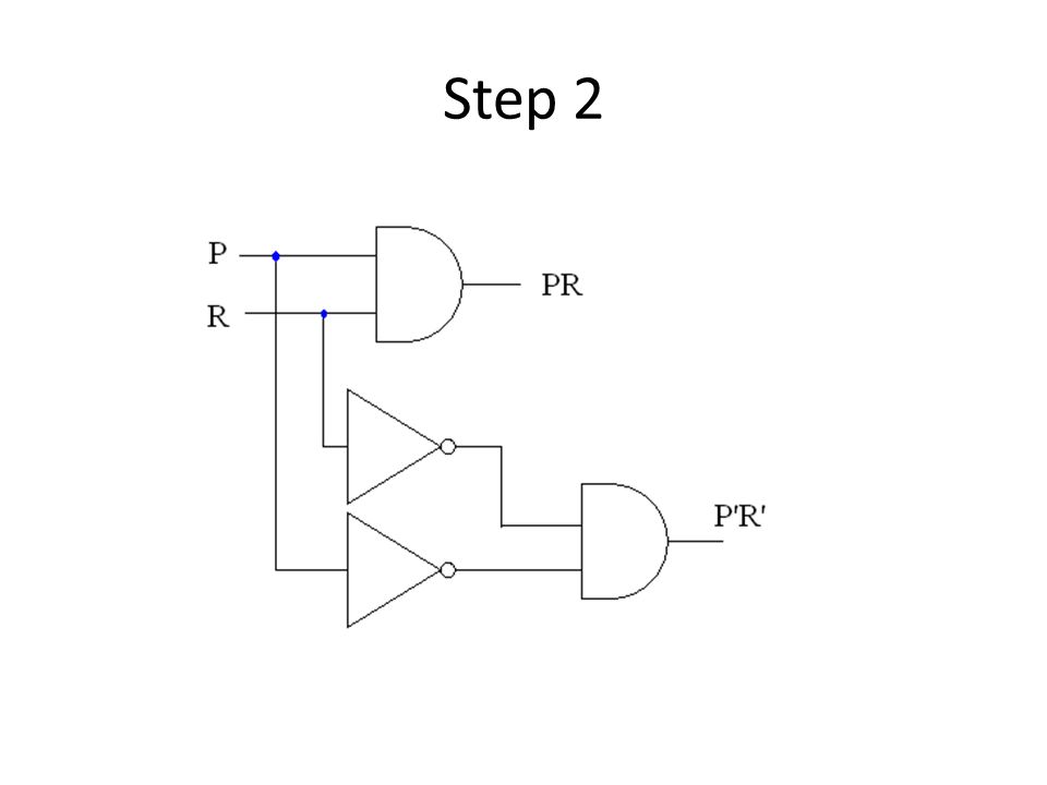
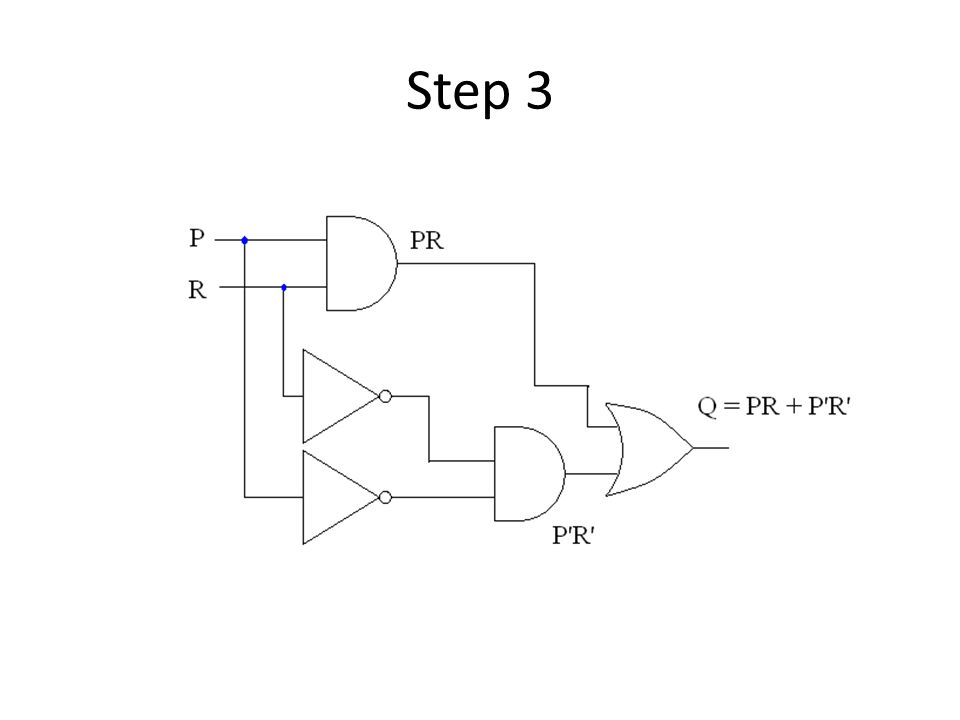
Finding the appropriate Expression PRPRP’R’P’R’PR + P’R’ 1110001 1000100 0101000 0001111 PR stands for P AND R P’ stands for NOT P M + N stands for M OR N Thus, we have Q = PR + P’R’

47
Building a Logical Circuit Now we want to build the a circuit for our computer using AND, OR and NOT gates which corresponds to logical expression Q = PR + P’R’ That is given inputs P and R (in 0 and 1) produces Q (in 0 and 1)
 produces Q (in 0 and 1)")
48
Big Picture

49
Step 1

50
Step 2

52
Step 3

54
Multiplexer A multi-way switch A two way multiplexer has two input lines, one select line and one output line. The select line determines the current from which input line should pass to output line.

55
Multiplexer

56
2-way MUX abselectoutput 1111 1101 1011 1000 0110 0101 0010 0000

57
2-way MUX Select input a if the select is 1. Select input b if the select is 0.

58
2-way MUX

59
Decoder Decoder is a circuit which has a single input and multiple outputs. It has one or more select lines. Select lines determine the current of input line should pass to which of the output lines.

60
Decoder

61
Two-way Decoder as0x1x0 1110 1001 0100 0000

Similar presentations