Download presentation
Presentation is loading. Please wait.

1
groups.yahoo.com/group/435_1

2
Chapter 1 Review of Power Electronics Converters

3
Power electronics refers to control and conversion of electrical power by power semiconductor devices wherein these devices operate as switches. "Electronic power converter" is the term that is used to refer to a power electronic circuit that converts voltage and current from one form to another. Rectifier converting an AC voltage to a DC voltage, Inverter converting a DC voltage to an AC voltage, Chopper or a switch-mode power supply that converts a DC voltage to another DC. Cycloconverter and cycloinverter converting an AC voltage to another AC voltage.

4
Harmonics It can be defined as a sinusoidal component of a periodic waves or quality having frequencies that are an integral multiple of the fundamental frequency. For Odd Functions: For Even Functions:

5
Odd Function Even Function Not Odd or Even Function

6
Individual voltage distortion (%)
The amount of distortion in the voltage or current waveform is qualified by means of a Total Harmonic Distortion (THD). Table (1.1) IEEE current distortion limits for general distribution systems (120 to 69kV) the maximum harmonic current distortion in percent of Individual Harmonic order (Odd Harmonics) THD % 35<n 23< n<35 17< n<23 11< n<17 n<11 5.0 0.3 0.6 1.5 2.0 4.0 <20 8.0 0.5 1.0 2.5 3.5 7.0 20<50 12.0 0.7 4.5 10.0 50<100 15.0 5.5 100<1000 20.0 1.4 6.0 >1000 (%) Individual voltage distortion (%) Bus voltage at PCC 5.0 3.0 69 kV and blow 2.5 1.5 kV through 161kV 1 kV and above
. Table (1.1) IEEE current distortion limits for general distribution systems (120 to 69kV) the maximum harmonic current distortion in percent of. Individual Harmonic order (Odd Harmonics) THD % 35<n. 23< n<35. 17< n<23. 11< n<17. n< < < < < >1000. (%) Individual voltage distortion (%) Bus voltage at PCC kV and blow kV through 161kV kV and above.")
7
Semiconductors Switch types
Diode Forward voltage drop =0.7 Volts for Silicon = 0.4 Volts for Germanium Peak Inverse voltage (PIV): Is the maximum voltage that a diode can withstand only so much voltage before it breaks down. Maximum Average Current: Is the average current that the diode can carry.
: Is the maximum voltage that a diode can withstand only so much voltage before it breaks down. Maximum Average Current: Is the average current that the diode can carry.")
8
Thyristor J3 J2 J1 Invented in 1957
consists of four layers of semiconductor materials (p-n-p-n) State J3 J2 J1 Gate Pulse ON Forward +ve OFF Reverse -ve
 State. J3. J2. J1. Gate Pulse. ON. Forward. +ve. OFF. Reverse. -ve.")
9
Thyristor types: Phase controlled thyristor(SCR)
Fast switching thyristor (SCR) Gate-turn-off thyristor (GTO) Bidirectional triode thyristor (TRIAC) DIAC Light activated silicon-controlled rectifier (LASCR)
 Gate-turn-off thyristor (GTO) Bidirectional triode thyristor (TRIAC) DIAC. Light activated silicon-controlled rectifier (LASCR)")
10
Gate Turn Off thyristor (GTO).
A GTO thyristor can be turned on by a single pulse of positive gate current like conventional thyristor It can be turned off by a pulse of negative gate current.

11
The GTO has the following advantage over thyristor:
Elimination of commutating components in forced commutation resulting in reduction in cost, weight and volume, Reduction in acoustic and electromagnetic noise due to the elimination of commutation chokes, Faster turn OFF permitting high switching frequency, Improved converters efficiency, and, It has more di/dt rating at turn ON.

12
The thyristor has the following advantage over GTO.
ON state voltage drop and associated losses are higher in GTO than thyristor, Triggering gate current required for GTOs is more than those of thyristor, Latching and holding current is more in GTO than those of thyristor, Gate drive circuit loss is more than those of thyristor, and, Its reverse voltage block capability is less than its forward blocking capability.

13
Bi-Directional thyristor (TRIAC).
TRIAC is used for the control of power in AC circuits. It is equivalent of two reverse parallel-connected SCRs with one common gate. Conduction can be achieved in either direction with an appropriate gate current. it is thus a bi-directional gate controlled thyristor with three terminals.

14
DIAC DIAC is like a TRIAC without a gate terminal.
DIAC conducts current in both directions depending on the voltage connected to its terminals. When the voltage between the two terminals greater than the break down voltage, the DIAC conducts and the current goes in the direction from the higher voltage point to the lower voltage one. The DIAC used in firing circuits of thyristors since its breakdown voltage used to determine the firing angle of the thyristor.

15
Current and future power semiconductor devices development direction.

16
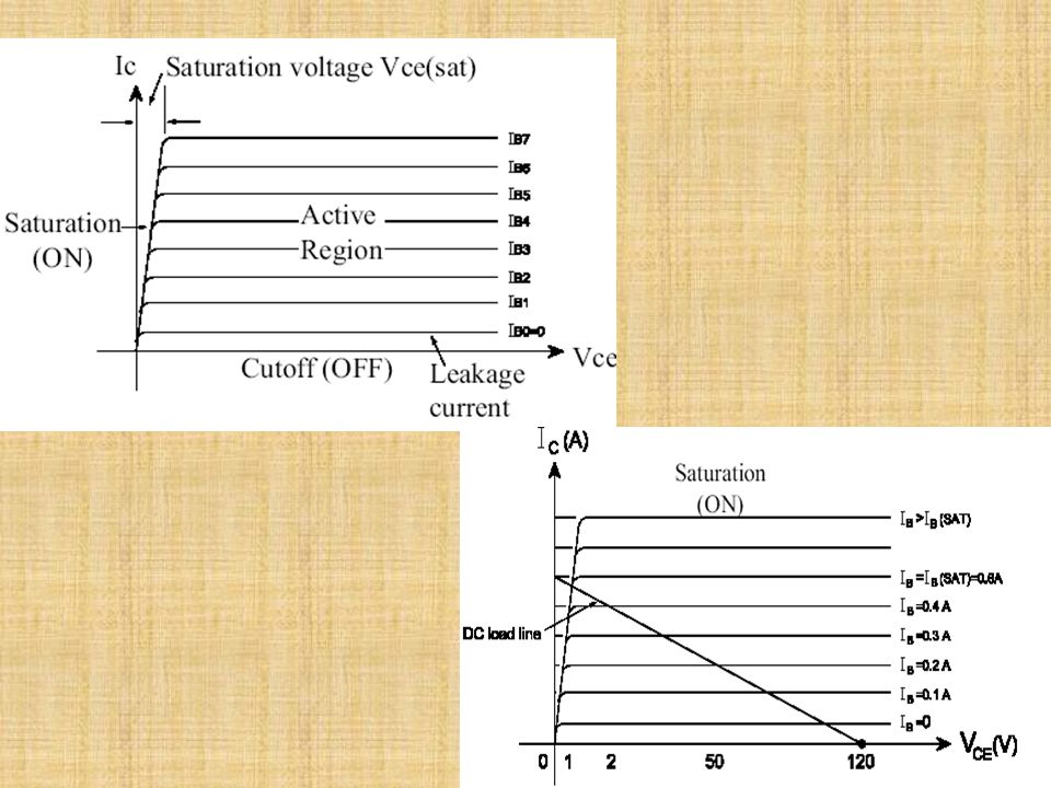
Bipolar Junction Transistor (BJT)
")
19
MOSFETs

21
Maximum current carrying capability.
1.7 General Power Semiconductor Switch Requirements Maximum current carrying capability. 2. Maximum voltage blocking capability. 3. Forward voltage drop during ON and its temperature dependency 4. Leakage current during OFF 5. Thermal capability 6. Switching transition times during both turn-on and turn-off 7. Capability to stand dV/dt when the switch is OFF or during turn-off 8. Capability to stand dI/dt when the switch is ON or during turn-on 9. Controllable dI/dt or dV/dt capability during switching transition 10. Ability to withstand both high current and voltage simultaneously 11. Switching losses 12. Control power requirement and control circuit complexity .

22
Insulated Gate Bipolar Transistors
The IGBT fundamentally changes the BJT current control into voltage control while maintaining the advantages of the BJT. The MOSFET has excellent dynamic and static performance. It dominates low voltage applications below 600 V. The IGBT is slower than the MOSFET but has better forward voltage drop above 600 V. It dominates applications from 600 to 3000 V.

Similar presentations


>")


 state maximum – exhibits.>")


>")