Download presentation
Presentation is loading. Please wait.

1
Local Area Networks Content Chapter 14: Advanced Review (Part I)
")
2
Switched Ethernet Ethernet Evolution Shared vs. Switched LANs Transparent Learning Spanning Tree Protocol Tutorial Questions Additional Notes

3
Ethernet Evolution n Developed in the mid-1980s as a shared bus LAN – Operated over coaxial cable – Used CSMA/CD channel access algorithm n Repeater and hubs (Layer 1 relays) extend distance – Number restricted to four between any two nodes on 10Mbps Ethernet n Bridges (Layer 2 relays) overcome restrictions on number of repeaters – Spanning Tree Protocol (IEEE 802.1D) addresses bridge resilience issues n Twisted pair cabling introduced in late 1980s – Reduced network diameter – More resilient than physical bus – Ethernet hub replaced repeater Repeater or bridge Bridge Hub CSMA/CD = carrier sense multiple access with collision detection
 extend distance – Number restricted to four between any two nodes on 10Mbps Ethernet n Bridges (Layer 2 relays) overcome restrictions on number of repeaters – Spanning Tree Protocol (IEEE 802.1D) addresses bridge resilience issues n Twisted pair cabling introduced in late 1980s – Reduced network diameter – More resilient than physical bus – Ethernet hub replaced repeater Repeater or bridge Bridge Hub CSMA/CD = carrier sense multiple access with collision detection")
4
Ethernet Evolution (continued) n Fast Ethernet standardized by mid-1990s – Supported on legacy UTP-3 and upcoming UTP-5 cabling – Reduced network diameter compared to 10Base-T n Auto-negotiating 10/100 interfaces self-configure speed and duplex mode – Flow control prevents overrun on 10 Mbps interfaces Data rate Cable types and distance limitations (meters) Coaxial cable (10Base5 and 10Base2) UTP-3 4-pair or UTP-5 (10Base-T and 100Base-TX) MMF (10Base-F and 100Base-FX) 10 Mbps 500 (no repeaters) 2500 (max. 4 repeaters) 100 (no repeaters) 500 (max. 4 repeaters 2000–3000 using 1 km FOIRL 100 Mbps —2052000 FOIRL = fiber optic inter-repeater link UTP = unshielded twisted pair
 100 (no repeaters) 500 (max. 4 repeaters 2000–3000 using 1 km FOIRL 100 Mbps — FOIRL = fiber optic inter-repeater link UTP = unshielded twisted pair.")
5
Gigabit Ethernet (GbE) n Gigabit operation standardized in 1998 – After Fibre Channel became established n Used Fibre Channel physical layer chips for 1-Gbps duplex operation – Needs fiber or enhanced quality copper (UTP-5e or better) n Shared (CSMA/CD) GbE added in 1999 – Restricted to single hub – Extended Ethernet collision window to 4096 bit times (4.096µsec) n Introduced compatibility issues with 10Base-T and 100Base-T – Has proved unpopular compared to switched GbE STP = shielded twisted pair Data rateDistance limitations (meters) STP 4- pair UTP 4- pair MMFSMF 1000 Mbps 25100 50/125: up to 550 62.5/125 up to 440 10,000
 n Gigabit operation standardized in 1998 – After Fibre Channel became established n Used Fibre Channel physical layer chips for 1-Gbps duplex operation – Needs fiber or enhanced quality copper (UTP-5e or better) n Shared (CSMA/CD) GbE added in 1999 – Restricted to single hub – Extended Ethernet collision window to 4096 bit times (4.096µsec) n Introduced compatibility issues with 10Base-T and 100Base-T – Has proved unpopular compared to switched GbE STP = shielded twisted pair Data rateDistance limitations (meters) STP 4- pair UTP 4- pair MMFSMF 1000 Mbps /125: up to /125 up to ,000")
6
Link Aggregation n Initially, a proprietary switch hardware feature – Available on Fast Ethernet and Gigabit Ethernet interfaces n Now standardized as IEEE 802.3ad – Further modifies LAN Layer 2 n Example – Aggregating four 100-Mbps inter-switch links gives aggregated bandwidth of 400 Mbps – Is cheaper than upgrading switches to GbE n Link Aggregation Control Protocol (LACP) negotiates load sharing – Fat pipes are treated as a single link by Spanning Tree Protocol MAC control MAC PHY New! MAC control MAC PHY … LLC Link Aggregation LLC = logical link control MAC = media access control PHY = physical Fat 400 Mbit/s pipe

7
10 Gigabit Ethernet (10GbE) n Standardized in 2003 as IEEE 802.3ae n Initially aimed at MAN/WAN links and storage area networks – Not designed for use in LAN n Switched full duplex only – CSMA/CD neither supported nor required n Current standard only supports optical fiber – Copper versions under investigation n Poses new engineering challenges! n Framing is compatible with earlier versions of Ethernet n Novel additions include – WAN interface definition for connecting to SDH/SONET MANs and WANs – New, high-specification multimode fiber type and PHY-PMD interface MAN = metropolitan area network PMD = physical medium dependent

8
10GbE Architecture Full duplex MAC XGMII or XAUI WWDM PHY (8B/10B coding) WWDM PHY (8B/10B coding) WWDM PMD (1310nm) WWDM PMD (1310nm) Serial LAN PHY (64/66B coding) Serial LAN PHY (64/66B coding) Serial WAN PHY (64/66B coding + WIS) Serial WAN PHY (64/66B coding + WIS) Serial PMD 850nm Serial PMD 1310nm Serial PMD 1500nm Serial PMD 850nm Serial PMD 1310nm Serial PMD 1500nm 10GBASE-CX4 10GBASE -SR -LR -ER 10GBASE -SW -LW-EW WIS = WAN interface sub-layer XAUI = 10Gbps attachment user interface WWDM = wideband wave division multiplexing XGMII = 10Gbps medium independent interface
 WWDM PHY (8B/10B coding) WWDM PMD (1310nm) WWDM PMD (1310nm) Serial LAN PHY (64/66B coding) Serial LAN PHY (64/66B coding) Serial WAN PHY (64/66B coding + WIS) Serial WAN PHY (64/66B coding + WIS) Serial PMD 850nm Serial PMD 1310nm Serial PMD 1500nm Serial PMD 850nm Serial PMD 1310nm Serial PMD 1500nm 10GBASE-CX4 10GBASE -SR -LR -ER 10GBASE -SW -LW-EW WIS = WAN interface sub-layer XAUI = 10Gbps attachment user interface WWDM = wideband wave division multiplexing XGMII = 10Gbps medium independent interface")
9
10GbE Operating Distances n 10GbE specification supports four fiber types – Two MMF types and two SMF types n Also allows three wavelengths: 850, 1310, and 1550 nm n Leads to a number of operating distances! – Table shows selection of distances (in meters) n Shorter distance is with 62.5/125-µ cable, longer one with 50/125-µ cable Wavelength Fiber type 850 nm1310 nm1550 nm 10GBASE-S26–300―― 10GBASE-L―10,000 10GBASE-E―― 30,000– 40,000 10GBASE-LX4300 10,000
 n Shorter distance is with 62.5/125-µ cable, longer one with 50/125-µ cable Wavelength Fiber type 850 nm1310 nm1550 nm 10GBASE-S26–300―― 10GBASE-L―10,000 10GBASE-E―― 30,000– 40,000 10GBASE-LX ,000.")
10
Switched Ethernet Ethernet Evolution Shared vs. Switched LANs Transparent Learning Spanning Tree Protocol Tutorial Questions Additional Notes

11
Hubs, Bridges and Switches n Hubs extend the collision domain – They are Layer 1 devices n Operate on bits n Bridges and switches are both Layer 2 LAN devices – Operate on MAC frames n Early bridges had limited connectivity – Often operated on one frame at a time n Switches have considerable connectivity potential – Can operate on several frames in parallel

12
Full Duplex Operation n Traditional CSMA/CD operates in shared (half duplex) mode – Host can either write to network or read from network n But not do both at same time n Traditional CSMA/CD hubs have CSMA/CD LAN ‘inside the box’ – Therefore are inherently half duplex n Extension to standard allows simultaneous reading and writing – Full duplex operation – Conditional on being supported by network device and host NIC n And there being only one NIC attached to device port NIC = network interface card Conventional hubs: inherently half duplex Systems on dedicated switch ports: could be half- or full duplex
 mode – Host can either write to network or read from network n But not do both at same time n Traditional CSMA/CD hubs have CSMA/CD LAN ‘inside the box’ – Therefore are inherently half duplex n Extension to standard allows simultaneous reading and writing – Full duplex operation – Conditional on being supported by network device and host NIC n And there being only one NIC attached to device port NIC = network interface card Conventional hubs: inherently half duplex Systems on dedicated switch ports: could be half- or full duplex")
13
n Modern CSMA/CD NICs available in two main forms – 100/100 or 10/100/1000 n Notation means they are capable of selecting – Speed at which they operate (10, 100 or 1000 Mbit/s) – And the mode at which they operate n Half- or full-duplex n Selection process carried out by an auto-negotiation protocol – Runs between NIC and switch – Also works with some hubs n Protocol attempts to negotiate highest throughput first – 1000Mbit/s or 100Mbit/s full-duplex operation n Then works down through list to lowest throughput – 10Mbit/s half-duplex n Full duplex operation is collision-free Auto-Negotiation Protocol
 – And the mode at which they operate n Half- or full-duplex n Selection process carried out by an auto-negotiation protocol – Runs between NIC and switch – Also works with some hubs n Protocol attempts to negotiate highest throughput first – 1000Mbit/s or 100Mbit/s full-duplex operation n Then works down through list to lowest throughput – 10Mbit/s half-duplex n Full duplex operation is collision-free Auto-Negotiation Protocol")
14
Bridges and Switches I n Bridges and LAN switches are MAC Layer relays – Used to interconnect LANs of same type – Use LAN MAC addressing – Operate on LAN frames 802.3,5,11, etc Physical: to match Data Link Protocol Bridge/LAN switch Layer 2 relay

15
Bridges and Switches II n Each port connects to a different collision domain – Supports parallel activity on each attached LAN segment n Transparent to routers and host operating systems layers 5/6/7: Application TCP, UDP IP 802.3,5,11,.. Physical 802.3,5,11,.. Physical 802.3,5,11,.. Physical 802.3,5,11,.. Physical layers 5/6/7: Application TCP, UDP IP 802.3,5,11,.. Physical

16
Shared LANs n Shared LANs developed for – File and print sharing (often on local servers) – Networked applications (may be on remote servers) – Bandwidth sharing, where dedicated bandwidth not required n Or dedicated bandwidth too expensive to justify for one system n LANs have used structured cabling systems since early 1990s – High specification cable interconnecting ‘wiring closets’ and network devices – Facilitate high transmission rates n Many of today’s wired LANs are CSMA/CD – Operating at 10/100 or 10/100/1000Mbit/s – Fully switched LANs increasingly popular n Wireless LANs (11 and 54 Mbit/s) also becoming common – Operate as shared media LANs n Discussed later in course n Switched LANs offer significant throughput increase over shared LANs
 – Networked applications (may be on remote servers) – Bandwidth sharing, where dedicated bandwidth not required n Or dedicated bandwidth too expensive to justify for one system n LANs have used structured cabling systems since early 1990s – High specification cable interconnecting ‘wiring closets’ and network devices – Facilitate high transmission rates n Many of today’s wired LANs are CSMA/CD – Operating at 10/100 or 10/100/1000Mbit/s – Fully switched LANs increasingly popular n Wireless LANs (11 and 54 Mbit/s) also becoming common – Operate as shared media LANs n Discussed later in course n Switched LANs offer significant throughput increase over shared LANs")
17
Switched vs. Shared Bandwidth n Example: Twelve users and four servers share 100Mbit/s LAN – All in same collision domain – Access time to shared channel increases as usage increases n Solution to increasing congestion: replace shared LAN with 10/100Mbit/s switch – Users divided into smaller collision domains n Each receives larger portion of bandwidth – Switch throughput at least port speed ½ number of ports n Eight-port switch supports up to 400Mbit/s throughput

18
Switched LANs n Switches commonly used for LAN-LAN interconnection – Usually interconnect same technologies n For example, CSMA/CD to CSMA/CD – Falling switch prices mean end of hub market n Switches available for all versions of CSMA/CD – 10, 100, 1000 and 10000Mbit/s n Rapidly decreasing support for older technologies – Token Ring (16 & 100Mbit/s), FDDI and ATM (25, 155 & 622Mbit/s) n CSMA/CD switches have become widespread due to – Their versatility n Support of different bit rates and media types – Their lower per-port cost than alternative technologies
, FDDI and ATM (25, 155 & 622Mbit/s) n CSMA/CD switches have become widespread due to – Their versatility n Support of different bit rates and media types – Their lower per-port cost than alternative technologies")
19
Ethernet Switches n Began to appear in mid-1990s as combined hub/bridges – Lower latency and lower per-port cost than bridges n Now commodity items – Multiple 10/100 interfaces at very low per-port cost n Unmanaged switches have become cost-efficient hub replacements – Many manufacturers no longer make hubs n Managed switches have CPU, memory and multitasking operating system – Support many additional features n VLANs n QoS n Multicast n And, of course, network management QoS = quality of service VLAN = virtual LAN

20
Ethernet Switches (continued) Late 1980s Mid-1990sLate 1990s Bridge Hub Switch Hub
 Late 1980s Mid-1990sLate 1990s Bridge Hub Switch Hub")
21
Multilayer Switches n Multilayer switches have both switching and routing modules – Operate at Layer 2 and Layer 3 – Often very high-speed and expensive devices n Typically equipped with hardware acceleration – Used in backbone (or ‘distribution’) networks Multilayer switch
 networks Multilayer switch")
22
Modern LAN Structure Wiring closet Workgroup servers Fiber links 10/100 switch Multilayer switch Site backbone Gigabit Ethernet/ATM Hub n Workgroups connected to small switches – Workgroup servers get dedicated ports – 10 and 100Mbit/s connections n Workgroup switches interconnected by multilayer switches – The backbone or distribution network – 100 and 1000Mbit/s connections used

23
Switched Ethernet Ethernet Evolution Shared vs. Switched LANs Transparent Learning Spanning Tree Protocol Tutorial Questions Additional Notes

24
n Bridge(switch) interfaces conform to specific IEEE LAN standard – For example, IEEE 802.3 Ethernet family n And operate according to the IEEE bridging standards – 802.1D: CDMA/CD transparent bridging and Spanning Tree – 802.1Q: Virtual LANs (VLANs) – 802.1p: Traffic classes and prioritization n The term switch is not standardized – Used in different ways to suit manufacturers’ marketing policies n For example, ‘multilayer switch’ n The term bridge defines a generic MAC-layer relay – Literature uses this term – We shall also use it in when discussing these devices in the context of a standard Relay logic MAC 1 MAC 2 Phys 1 Phys 2 Standards and Terminology
 interfaces conform to specific IEEE LAN standard – For example, IEEE Ethernet family n And operate according to the IEEE bridging standards – 802.1D: CDMA/CD transparent bridging and Spanning Tree – 802.1Q: Virtual LANs (VLANs) – 802.1p: Traffic classes and prioritization n The term switch is not standardized – Used in different ways to suit manufacturers’ marketing policies n For example, ‘multilayer switch’ n The term bridge defines a generic MAC-layer relay – Literature uses this term – We shall also use it in when discussing these devices in the context of a standard Relay logic MAC 1 MAC 2 Phys 1 Phys 2 Standards and Terminology")
25
Transparent Learning Bridges n Each interface operates in promiscuous mode – Receives and processes all frames from LAN attached to that interface n Devices build a MAC address table – Inspect each frame header – Record frame’s source MAC address (MAC SA ) and the port number on which the frame entered n Process is called transparent learning – Determines how data frames processed subsequently Port 1 Port 2 MAC A MAC N MAC G MAC K MAC address table MAC SA = A MAC DA = K IP SA = A IP DA = K Upper layer info G A B C T K N 1 2 B
 and the port number on which the frame entered n Process is called transparent learning – Determines how data frames processed subsequently Port 1 Port 2 MAC A MAC N MAC G MAC K MAC address table MAC SA = A MAC DA = K IP SA = A IP DA = K Upper layer info G A B C T K N 1 2 B")
26
The Three F’s n Bridge extracts MAC DA from incoming frame headers and looks it up in MAC address table – Device then makes forwarding decision n Forwards frame to systems on different ports – To ensure frame reaches correct LAN segment n Filters frames between systems on same port – Since systems on same port, normal MAC-level addressing ensures that frame reaches destination – No further action required by bridge n Floods broadcast and multicast frames – Bridge also required to flood frames with unknown MAC destination addresses – Flooding means sending a copy of the incoming frame to all other ports T unknown: flooded B G: filtered A K: forwarded G A B CT HKN 1 2

27
Static Filtering n Older bridges could be programmed with static filters n Examples – Filter frames to system G arriving on port 1 – Filter AppleTalk frames arriving at port 2 n This function eventually taken over by routers All G: filtered G A B CT HKN 1 2 All AppleTalk: filtered

28
Port 1 Port 2 Port 3 LRA MSB NTC G H MAC Address Tables n Identify the port on which known systems can be reached – Could be via other switches R M A BCGH L N S T SW1 SW2 1 2 3 1 2 3 Port 1 Port 2 Port 3 AGL BHM CN R S T

29
Switched Ethernet Ethernet Evolution Shared vs. Switched LANs Transparent Learning Spanning Tree Protocol Tutorial Questions Additional Notes

30
Single Points of Failure n A single bridge interconnecting two LANs constitutes a single point of failure – More than one user affected if device fails LAN 2 LAN 1 LAN 5 LAN 3LAN 4 G A B C T KN 1 2 B

31
What About Using Extra Bridges for Resilience? n Bridges learn MAC addresses as usual – For example, a frame from H to P n Each bridge queues a copy of the frame for forwarding to the other LAN segment n Other port on each bridge receives copy of frame – Notes new port for H – Queues frame for forwarding to original LAN – And looping starts to occur n … but when does it stop? n Suppose you were to use two extra bridges instead of just one? – Or there is more than one loop? n Bridges use the Spanning Tree Protocol to resolve the problems of looping frames B1 1 2 B2 1 2 N P F G H Q

32
n Supported by all MAC-Layer bridges (switches) – Runs automatically (unless disabled) n Bridges send each other topology messages (‘BPDUs’) to build the spanning tree – A loop-free topology n When the protocol has run, certain bridge ports will forward MAC data frames – Other ports will be blocked * – Leaves a single path between any two LANs n Inter-switch links treated as LANs in this context n Once configured, protocol periodically re-affirms topology – Reconfigures spanning tree if topology fails The Spanning Tree Protocol (IEEE 802.1D) B1 1 2 B2 1 2 N P F G H Q BPDU = bridge protocol data unit* All ports continue to receive BPDUs, even if blocked for data frames
 – Runs automatically (unless disabled) n Bridges send each other topology messages (‘BPDUs’) to build the spanning tree – A loop-free topology n When the protocol has run, certain bridge ports will forward MAC data frames – Other ports will be blocked * – Leaves a single path between any two LANs n Inter-switch links treated as LANs in this context n Once configured, protocol periodically re-affirms topology – Reconfigures spanning tree if topology fails The Spanning Tree Protocol (IEEE 802.1D) B1 1 2 B2 1 2 N P F G H Q BPDU = bridge protocol data unit* All ports continue to receive BPDUs, even if blocked for data frames")
33
Motivation for Spanning Tree A collection of LANs that are interconnected by a set of bridges, The interconnection may have redundant to increase reliability, Redundancy introduce loops which defeats the objective because multiple reception of same packets (diff. routes) and routing back to source are possible, A spanning tree create a single virtual route, although multiple physical routes are there. Setting up a Spanning Tree The bridge (B) with lowest ID is selected as Root Bridge (RB), The root port (RP) of B, other than RB, is a port of B such that: the link(RP,RB) is least among all ports of B, where least cost means minimum number of hops, least delay, or maximum bandwidth, There should be one designated B (DB) for each LAN-X. DB is defined as a B directly connected to LAN-X such that Path(LAN,RB) is least is route is done through DB. There should be a designated port (DP/DB) connecting DB to LAN-X, if ties then lowest ID. Make Root Ports (RPs) and Designated Ports (DPs/DB) as forwarding ports and all the other as blocking ports. The results: packets flowing through RPs and DPs/DB follow a spanning tree route without loops. The Spanning Tree Protocol (IEEE 802.1D)
 and routing back to source are possible, A spanning tree create a single virtual route, although multiple physical routes are there. Setting up a Spanning Tree The bridge (B) with lowest ID is selected as Root Bridge (RB), The root port (RP) of B, other than RB, is a port of B such that: the link(RP,RB) is least among all ports of B, where least cost means minimum number of hops, least delay, or maximum bandwidth, There should be one designated B (DB) for each LAN-X. DB is defined as a B directly connected to LAN-X such that Path(LAN,RB) is least is route is done through DB. There should be a designated port (DP/DB) connecting DB to LAN-X, if ties then lowest ID. Make Root Ports (RPs) and Designated Ports (DPs/DB) as forwarding ports and all the other as blocking ports. The results: packets flowing through RPs and DPs/DB follow a spanning tree route without loops. The Spanning Tree Protocol (IEEE 802.1D).")
34
Spanning Tree Overview n Spanning Tree operation based on two device parameters – Bridge identifier, or BID – Notional cost of leaving bridge on given port n Bridges flood BPDUs to determine bridge with lowest BID – This bridge becomes Root Bridge n Other bridges then 1. Identify their root ports n Those with lowest cost path to Root Bridge 2. Identify any designated ports n Those responsible for forwarding frames away from the Root 3. Block their non-designated ports n Those with higher-cost path to Root 10 15 10 5 bridge 1 priority 10 1 2 1 2 N P F G H Q bridge 2 priority 1 Port costs

35
Bridge Identifiers n Two fields concatenated into 64-bit number – 16-bit priority and 48-bit MAC address n Priority is at most significant end of number n Manufacturers normally select default value for priority – Standard recommends default of 32768 n Reducing priority increases bridge’s Root eligibility – For example, reducing the priority to 32700 n MAC address acts as tie-breaker if all priorities equal Priority Sending port’s MAC address MAC = 0060.6475.6bc0MAC = 0060.6475.6b00MAC = 0060.6475.6d05

36
Port cost n Every bridge/switch port has outgoing port cost – Older bridges used 10 9 /bandwidth by default – Newer versions use non-linear scale of IEEE 802.1D – Port costs can usually be set manually n Root path cost is the sum of (outgoing) path costs to Root from current bridge – Cost is 0 for all Root ports BandwidthCost 10 Mbps100 16 Mbps62 45 Mbps39 100 Mbps19 155 Mbps14 622 Mbps6 1 Gbps4 10 Gbps2 10019 Root path cost = 138 Outgoing cost = 19 Outgoing cost = 100 100 Mbps 10 Mbps Root bridge
 path costs to Root from current bridge – Cost is 0 for all Root ports BandwidthCost 10 Mbps Mbps62 45 Mbps Mbps Mbps Mbps6 1 Gbps4 10 Gbps Root path cost = 138 Outgoing cost = 19 Outgoing cost = Mbps 10 Mbps Root bridge")
37
LAN Switching Hubs and Media Bridges and Switches Transparent Learning Spanning Tree Protocol Spanning Tree Examples Note on VLANs

38
Two-Switch Example Stage I: Root Discovery n Both bridges flood BPDUs with Root Bridge = self for a preset period n At end of this stage, B2 found to have lowest BID – Priorities same (32768) – B2’s MAC address lower than B1’s n B2 becomes Root Bridge 32768 0060.6475.6b00 0060.6475.6bc0B1’s BID B2’s BID B1 Priority 32768 0060.6475.6bc0 1 2 1 2 N P F G H Q LAN 1 (10Mbps) B2 Priority 32768 0060.6475.6b00 LAN 2 (10Mbps)
 – B2’s MAC address lower than B1’s n B2 becomes Root Bridge b bc0B1’s BID B2’s BID B1 Priority bc N P F G H Q LAN 1 (10Mbps) B2 Priority b00 LAN 2 (10Mbps)")
39
Stage II: Find lowest cost root path n Non-root bridge(s) determine lowest-cost path to root n Equal-lowest-cost paths decided by series of tie-breakers 1. Upstream bridge with lowest BID n Where more than one bridge available 2. Lowest port ID on bridge n Where bridge has lowest cost path from more than one port n Defaults to lowest port number n B1 has two lowest cost paths to root – Port 1 is lower port number than port 2 n B1 port 1 becomes root port – Alternate path via Port 2 will be blocked n Becomes a non-designated port LAN 1 (10Mbps) LAN 2 (10Mbps) B1 Priority 32768 0060.6475.6bc0 1 2 1 2 F G H B2 Priority 32768 0060.6475.6b00 Root path Cost = 100 Root path Cost = 100 N P Q
 LAN 2 (10Mbps) B1 Priority bc F G H B2 Priority b00 Root path Cost = 100 Root path Cost = 100 N P Q.")
40
Stage III: Finalize Spanning Tree n Root Bridge – Places all active ports in forwarding state n All active ports on root bridge are designated ports n Non-root bridges modify port states – Root port placed into forwarding state n B1, port 1 – Designated port(s) placed into forwarding state n In this example, B1 has no designated ports – Non-designated ports moved to blocking state n B1, port 2 n Root bridge periodically sends out Root BPDU to reaffirm topology LAN 1 (10Mbps) LAN 2 (10Mbps) B1 Priority 32768 0060.6475.6bc0 1 2 1 2 F G H B2 Priority 32768 0060.6475.6b00 N P Q RP(F) NDP(B) DP(F) X
 placed into forwarding state n In this example, B1 has no designated ports – Non-designated ports moved to blocking state n B1, port 2 n Root bridge periodically sends out Root BPDU to reaffirm topology LAN 1 (10Mbps) LAN 2 (10Mbps) B1 Priority bc F G H B2 Priority b00 N P Q RP(F) NDP(B) DP(F) X")
41
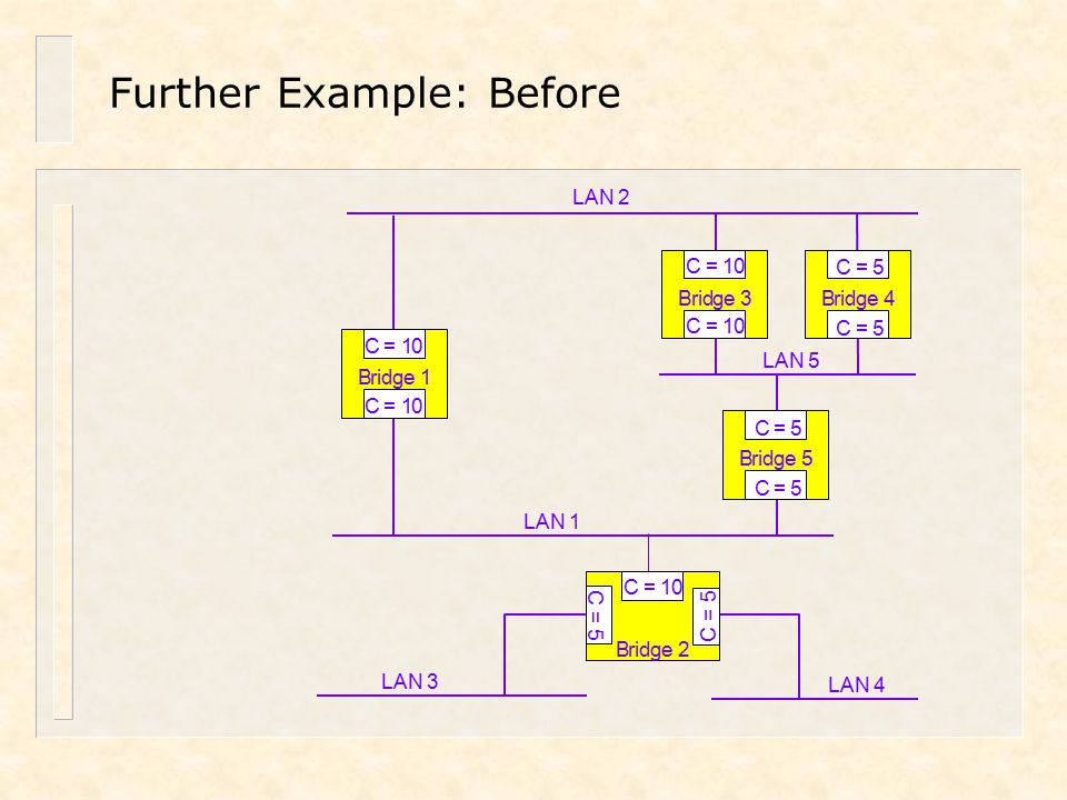
Further Example: Before

43
Stage I: Identify Root Bridge Bridge with lowest BID becomes Root LAN 2

44
Stage II: Identify Forwarding Ports Notes 1.RPC = root path cost 2.Bridge 2 has only one root path 3.Bridges 4 & 5 tie on lowest path to Root for LAN 5 –Lowest BID is tie-breaker (4) 4.All Root Bridge ports are designated ports with RPC of zero Notes 1.RPC = root path cost 2.Bridge 2 has only one root path 3.Bridges 4 & 5 tie on lowest path to Root for LAN 5 –Lowest BID is tie-breaker (4) 4.All Root Bridge ports are designated ports with RPC of zero
 4.All Root Bridge ports are designated ports with RPC of zero Notes 1.RPC = root path cost 2.Bridge 2 has only one root path 3.Bridges 4 & 5 tie on lowest path to Root for LAN 5 –Lowest BID is tie-breaker (4) 4.All Root Bridge ports are designated ports with RPC of zero")
45
Stage III: Finalize Spanning Tree B1 The Spanning Tree B2 B4 B5 B3 L1 L4 L5 L2 L3 Key = Forwarding = Blocking Key = Forwarding = Blocking X

46
Summary n Variety of media are used on CSMA/CD LANs – But the most common media today are twisted pair and optical fibre n LAN switches have replaced bridges – Behave exactly like bridges – But have higher connectivity and throughput n Bridges and switches divide LANs into separate collision domains – But interconnected LANs are still a single broadcast domain n Modern LANs must have some degree of fault tolerance – Provided by installing additional switches and links n CSMA/CD bridges use the Spanning Tree Protocol to create a loop-free topology that spans whole Layer 2 domain n Virtual LANs provide additional traffic control in switched LANs

47
Switched Ethernet Ethernet Evolution Shared vs. Switched LANs Transparent Learning Spanning Tree Protocol Tutorial Questions Additional Notes

48
Tutorial Questions 1. At which OSI layers do bridges and switches operate? 2. What is meant by a transparent learning bridge? 3. How, and why, are frames to unknown destination addresses treated like broadcasts and multicasts? 4. What is the reason for using Spanning Tree and why is it required? 5. Full duplex operation is likely to be most beneficial for what types of host?

49
Tutorial Questions (continued) 6.In the diagram below, there are three hosts systems, A, B & C and one server, D all connected to 10Mbit/s LAN segments Briefly describe how a frame from A reaches D, assuming that all systems have just been switched on; include a description of how the ARP from A is processed by the bridges. Show the entries of the port tables in bridges B1 and B2, once the location of all three systems have been determined. A B C D B1 B2 LAN 2 (10Mbit/s) LAN 1 (10Mbit/s) LAN 3 (10Mbit/s)
 LAN 1 (10Mbit/s) LAN 3 (10Mbit/s).")
50
Tutorial Questions (continued) 7.Here is the LAN diagram again, but an additional bridge, B3, has been connected as shown, requiring the use of Spanning Tree. (The diagram shows the MAC address of each bridge, all of which have equal priority.) Re-draw the diagram showing the Root Bridge and labelling all bridge ports as root ports, designated ports or non-designated ports and showing which ports are forwarding and which are blocking. Show one way in which you could connect the above LANs and server, with another LAN segment and three further servers into a single eight-port switch. A B C D B1 0000.0c07.ac01 B2 0004.2875.c860 B3 0006.28c3.03c0 LAN 1 (10Mbit/s) LAN 2 (10Mbit/s) LAN 3 (10Mbit/s)
 Re-draw the diagram showing the Root Bridge and labelling all bridge ports as root ports, designated ports or non-designated ports and showing which ports are forwarding and which are blocking. Show one way in which you could connect the above LANs and server, with another LAN segment and three further servers into a single eight-port switch. A B C D B c07.ac01 B c860 B c3.03c0 LAN 1 (10Mbit/s) LAN 2 (10Mbit/s) LAN 3 (10Mbit/s).")
51
Switched Ethernet Ethernet Evolution Shared vs. Switched LANs Transparent Learning Spanning Tree Protocol Tutorial Questions Additional Notes

52
Repeaters and Hubs n Operate at the Physical Layer – Physical Layer relays – Unit of transfer is the bit n Extend domain of MAC protocol – The collision domain – Repeat incoming bits to other ports n MAC frames seen by all systems n Systems contend for extended communication channel n Support a variety of media types – Allows old style shared coaxial segments to be connected to modern twisted pair segments n Most hubs just multi-port repeaters relay logic Phys 1 Phys 2 Coaxial LAN segment hub Ph 1 relay logic

53
10BaseT Hubs n Have separate 10BaseT ports for each system – Enhances LAN resilience – Works in conjunction with structured cabling systems – Can be cascaded to interconnect multiple LAN segments n Maximum number of hubs/repeaters allowed between any two systems varies with media type and bit rate – 10BaseT n No more than 4 (same as for coax cable) – 100BaseT n No more than 2 with twisted pair cable Coaxial LAN segment
 – 100BaseT n No more than 2 with twisted pair cable Coaxial LAN segment")
54
CSMA/CD Media Types & Limitations n LAN segment lengths limited by two factors – The operation of the CSMA/CD protocol – The media type n Strictly, the bandwidth of the media n CSMA/CD collision window sets maximum amount of time for detecting a collision – Specified by the 10Base5 standard as 51.2µs at 10 Mbit/s n Equal to 512 bit times – At 100Mbit/s the collision window becomes 5.12µs (still 512 bit times) n Different media have different transmission qualities – Structured cabling systems specify maximum distance from wiring closet to desktop system of 100 metres n Standards committees meet this criterion for all desktop LAN speeds CSMA/CD = carrier sense multiple access with collision detection
 n Different media have different transmission qualities – Structured cabling systems specify maximum distance from wiring closet to desktop system of 100 metres n Standards committees meet this criterion for all desktop LAN speeds CSMA/CD = carrier sense multiple access with collision detection")
55
CSMA/CD Media Types & Limitations (continued) Media Type Data rate (Mbit/s) Max. cable length (metres) Max. Number of stations per cable Twisted Pair 10, 100, 1000 100Two Thin Coax. 1018530 Thick Coax 10500100 Optical Fibre 10, 100, 1000, 10000 Depends on fibre type and data rate Two
 Max. Number of stations per cable Twisted Pair 10, 100, Two Thin Coax Thick Coax Optical Fibre 10, 100, 1000, Depends on fibre type and data rate Two.")
56
Evolving Technologies for Ethernet LAN Interconnection 1980 – 1984 Shared Ethernet deployed International LAN standards developed 1985 – 1989 Bridges used for LAN interconnection to limit size of collision domains, with Spanning Tree facilitating bridge redundancy; routers used for LAN-WAN interconnection 1990 - 1994 High-speed, low-cost routers become alternatives to bridges ‘Backbone routers’ developed for site interconnections 1995 - 1999 VLAN-capable switches replace bridges and LAN routers 100Mbit/s Ethernet becomes common, GbE developed 2000 -Switched access and VLAN deployment become common 10GbE developed, Ethernet switches become QoS- enabled

57
The Rise and Fall of the LAN Router n In early 1990s, small routers introduced to limit size of broadcast domains – Became cheap, and fast, enough to use in LANs n But routers operate at Network Layer – Require configuration (are not plug-and-play) – Have higher per-port cost than equivalent bridge n LAN switches began to replace bridges in mid-1990s – Still operate at Layer 2 – Have much lower per-port cost than routers – Can be operated in plug-and-play mode or configured n For example with management and VLAN information n Routers still required for inter-site and inter-VLAN communication – Particularly suitable for interconnecting different technologies n For example, CSMA/CD & Frame Relay, CSMA/CD & Token Ring
 – Have higher per-port cost than equivalent bridge n LAN switches began to replace bridges in mid-1990s – Still operate at Layer 2 – Have much lower per-port cost than routers – Can be operated in plug-and-play mode or configured n For example with management and VLAN information n Routers still required for inter-site and inter-VLAN communication – Particularly suitable for interconnecting different technologies n For example, CSMA/CD & Frame Relay, CSMA/CD & Token Ring")
Similar presentations


>")

 and point-to-point links, Ethernet,>")


>")


 max distance between any two nodes without repeaters thin coaxial.>")
 Layer 2 Switching and Virtual LANs (VLANs) Local Area Network (LAN) Layer 2 Switching and Virtual LANs (VLANs) Chapter 6.>")
