Download presentation
Presentation is loading. Please wait.

1
Chapter 7 Multiuser Detection

2
We have discussed a simple method of MAI suppression in Chapter 6.
The idea of MAI suppression stems from the single-user detection philosophy, in which we treat signals from other users as interference. In this chapter, we will introduce another way, namely multiuser detection, to tackle the near-far problem. In the paradigm of multiuser detection, we jointly detect data signals from all the users. There is not MAI since signals form all users are treated as the desired signals. However, one should note that this does not mean that we do not need to design spreading sequences with “good” correlation properties for the users.

3
For example, if two users use exactly the same sequence spreading sequence and their transmissions are synchronous, there is not way we can reliably resolve the data signals of the two users from the received signal even if we detect them jointly. On the other hand, with properly designed sequences, the near-far problem is solved implicitly by performing multiuser detection. Theoretically, receivers based on multiuser detection usually outperform, but are usually more complex than, receivers based on single-user detection. The applicability of multiuser receivers depends on system design issues, such as the security of joint detection, the implementation complexity, and the availability of information required to perform multiuser detection.

4
For example, let us consider a typical wireless cellular system.
It would be difficult to employ multiuser receivers at the mobile units for forward-link transmission because of the limitation on the implementation complexity and the availability of information about other users. However, multiuser detection could be a viable choice in the base-station for reverse-link transmission. In this chapter, we will introduce some common multiuser detection techniques. We will start with the optimal multiuser receiver and then discuss some suboptimal but simpler receivers. As we mentioned in Chapter 6, we will also discuss some single-user MAI suppression receivers which happen to be specializations of the suboptimal multiuser receivers described in this chapter.

5
7.1 Maximum Likelihood Sequence (MLS) receiver
First, let us spell out the mathematical model of DS-CDMA system we use throughout the chapter. Basically, we consider the same asynchronous DS-CDMA model in Section 6.1 with the following simplifications: Short sequences are employed and for notational convenience, we use ak(t) to represent one period of the spreading signal, i.e., A finite number of symbols are transmitted for each user. For the kth user, we define its symbol vector as
 to represent one period of the spreading signal, i.e., A finite number of symbols are transmitted for each user. For the kth user, we define its symbol vector as.")
6
Hence, the received signal can be written as
where n(t) is AWGN with power spectral density N0, The form of (7.3) actually embodies the idea of multiuser detection — all the user’s signals are treated as desired signals.
 is AWGN with power spectral density N0, The form of (7.3) actually embodies the idea of multiuser detection — all the user’s signals are treated as desired signals.")
7
With this in mind, we note that (7. 3) is exactly the same as (1
With this in mind, we note that (7.3) is exactly the same as (1.1), the simple M-ary signaling in an AWGN channel, except that we have 2K(2M+1) possible “symbols” and the symbol duration is much longer than T in the multiuser case here. The whole development in Section 1.1 applies and the ML receiver decides b, all the bits of the users, which maximizes the following correlation metric, Let us define
 is exactly the same as (1.1), the simple M-ary signaling in an AWGN channel, except that we have 2K(2M+1) possible symbols and the symbol duration is much longer than T in the multiuser case here. The whole development in Section 1.1 applies and the ML receiver decides b, all the bits of the users, which maximizes the following correlation metric, Let us define.")
8
where Then the correlation metric in (7.6) can be written as
 can be written as")
9
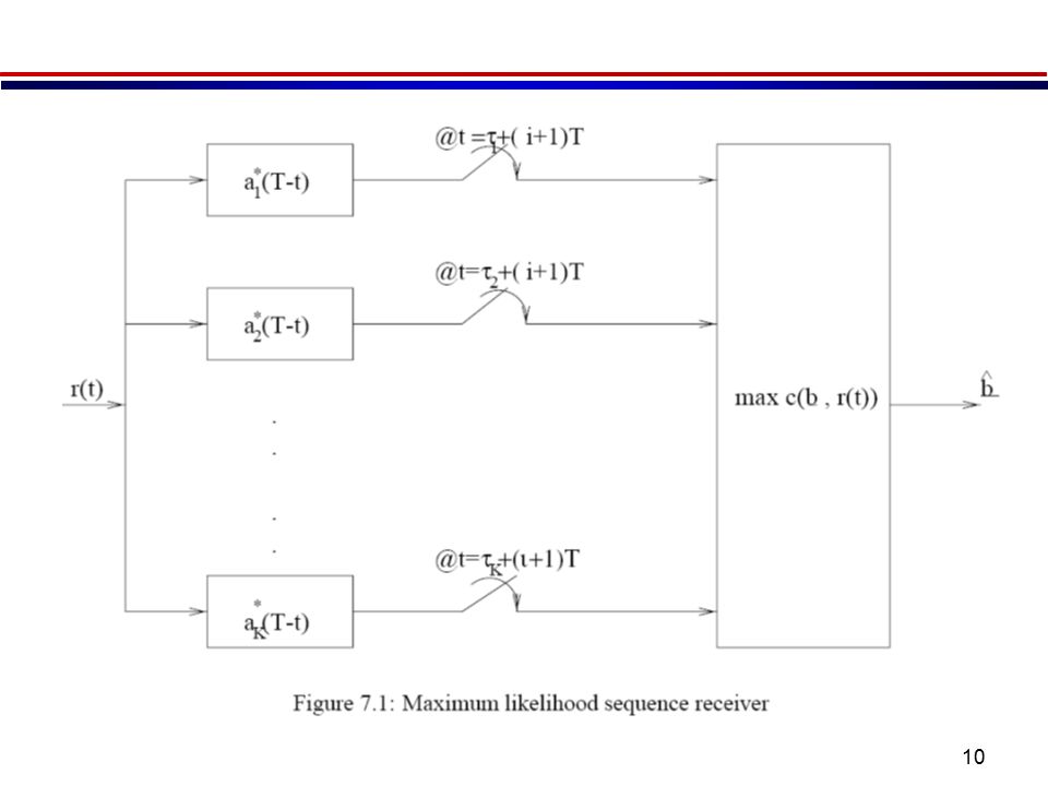
From (7.11), we see that the statistics
are sufficient for the detection of b. As a result, the MLS receiver consists of a branch of matched filters which are matched to the spreading signals of the users as shown in Figure 7.1.

11
We note that a brute-force maximization of c(b; r(t)) would require a complexity of O(2K(2M+1)) which is by no means practical. It has been shown [1] that the MLS receiver can be implemented by the Viterbi algorithm with a complexity of O(2K-1) in a feed-forward fashion. This makes the MLS receiver practical when the number of users in the system is small, say, less than 10. Unfortunately, this is seldom the case for a practical CDMA system. Therefore the use of the MLS receiver is limited.
 in a feed-forward fashion. This makes the MLS receiver practical when the number of users in the system is small, say, less than 10. Unfortunately, this is seldom the case for a practical CDMA system. Therefore the use of the MLS receiver is limited.")
12
Moreover, we note that in order to implement the MLS receiver, besides knowing all the spreading sequences, we need to estimate the delays, carrier phases as well as the receiver power of all the users. Usually, this estimation is very hard to achieve and thus further limits the usefulness of the MLS receiver. Nevertheless, the MLS receiver is important since it gives us a benchmark to gauge the performances of other sub-optimal receivers. It is shown in [1] that the MLS receiver is near-far resistant. We also note that the MLS receiver minimizes the joint error probability of all the bits of all the users. Another possible approach is to minimize the error probability of each individual bit.

13
Optimum Detectors Consider a DS/CDMA network with K users, each of which uses PSK to transmit a block of N binary symbols. A jointly optimum detector makes collective symbol decisions for K received signals based on the maximum a posteriori (MAP) criterion. The individually optimum detector selects the most probable set of symbols of a single desired signal from one user based on the MAP criterion, thereby providing the minimum symbol error probability. In nearly all applications, jointly optimum decisions would be preferable because of their lower complexity and because both types of decisions will agree with very high probability unless the symbol error probability is very high.
 criterion. The individually optimum detector selects the most probable set of symbols of a single desired signal from one user based on the MAP criterion, thereby providing the minimum symbol error probability. In nearly all applications, jointly optimum decisions would be preferable because of their lower complexity and because both types of decisions will agree with very high probability unless the symbol error probability is very high.")
14
Assuming equally likely symbols are transmitted, the jointly optimum MAP detector is the same as the jointly optimum maximum-likelihood detector, which is henceforth referred to as the optimum detector. For synchronous communications in the presence of white Gaussian noise, the symbols are aligned in time, and the detection of each symbol of the desired signal is independent of the other symbols. Thus, the optimum detector can be determined by considering a single symbol interval Let dk denote the symbol transmitted by user k. The customary (highly idealized) assumption is that a perfect carrier synchronization enables the receiver to remove a common carrier frequency and phase.
 assumption is that a perfect carrier synchronization enables the receiver to remove a common carrier frequency and phase.")
15
Thus, the composite baseband received signal is
(7-12) Ak is the received symbol amplitude from user k pk(t) is the unit-energy spreading waveform of user k dk= ±1 n(t) is the baseband Gaussian noise. Assuming that all possible values of the symbol vector are equally likely, the optimum detector is the maximum-likelihood detector, which selects the value of d that minimizes the log-likelihood function (7-13)
 Ak is the received symbol amplitude from user k. pk(t) is the unit-energy spreading waveform of user k. dk= ±1. n(t) is the baseband Gaussian noise. Assuming that all possible values of the symbol vector are equally likely, the optimum detector is the maximum-likelihood detector, which selects the value of d that minimizes the log-likelihood function. (7-13)")
16
The vector of the cross correlations between r(t) and the spreading sequences is denoted by
(7-14) Let A denote the K × K diagonal matrix with diagonal components Let R denote the K × K correlation matrix with elements (7-15) where because the spreading waveforms are normalized to unit energy. Expanding (7-13), dropping an integral that is irrelevant to the selection of d, and then substituting (7-14) and (7-15), we find that the maximum-likelihood detector selects the value of d that maximizes the correlation metric (7-16)
 Let A denote the K × K diagonal matrix with diagonal components. Let R denote the K × K correlation matrix with elements. (7-15) where because the spreading waveforms are normalized to unit energy. Expanding (7-13), dropping an integral that is irrelevant to the selection of d, and then substituting (7-14) and (7-15), we find that the maximum-likelihood detector selects the value of d that maximizes the correlation metric. (7-16)")
17
This equation implies that the optimum detector uses a filter bank of K parallel correlators.
Correlator k computes rk given by (7-14) and can be implemented as the single-user detector. Equation (7-16) also indicates that the K spreading sequences must be known so that R can be calculated, and the K signal amplitudes must be estimated. Short spreading sequences are necessary or R must change with each symbol. The optimum detector is capable of making joint symbol decisions for all K signals or merely the symbol decisions for a single signal.
 and can be implemented as the single-user detector. Equation (7-16) also indicates that the K spreading sequences must be known so that R can be calculated, and the K signal amplitudes must be estimated. Short spreading sequences are necessary or R must change with each symbol. The optimum detector is capable of making joint symbol decisions for all K signals or merely the symbol decisions for a single signal.")
18
As an example, consider synchronous communications with K = 2 and
After the elimination of terms irrelevant to the selection, (7-16) implies that the optimum detector evaluates for the four pairs with d1= ±1 and d2= ±1. The pair that maximizes C provides the decisions for d1 and d2. In view of both the computational requirements and the parameters that must be estimated, it is highly unlikely that the optimum multiuser detector will have practical applications. Subsequently, alternative suboptimal multiuser detectors are considered.
 implies that the optimum detector evaluates. for the four pairs with d1= ±1 and d2= ±1. The pair that maximizes C provides the decisions for d1 and d2. In view of both the computational requirements and the parameters that must be estimated, it is highly unlikely that the optimum multiuser detector will have practical applications. Subsequently, alternative suboptimal multiuser detectors are considered.")
19
Decorrelating detector
The decorrelating detector may be derived by maximizing the correlation metric of (7-16) without any constraint on d. For this purpose, the gradient of f with respect to the real-valued n-dimensional vector x is defined as the column vector with components From this definition, it follows that for column vectors x and y (7-17) (7-18) Applying (7-17) and (7-18) to the correlation metric, we find that implies that C is maximized by where (7-19)
 without any constraint on d. For this purpose, the gradient of f with respect to the real-valued n-dimensional vector x is defined as the column vector with components. From this definition, it follows that for column vectors x and y. (7-17) (7-18) Applying (7-17) and (7-18) to the correlation metric, we find that implies that C is maximized by where. (7-19)")
20
Since each component of the vector Ad' is a positive multiple of the corresponding component of d', there is no need to solve for d'. A suitable estimate of the transmitted bits is (7-20) The decorrelating detector, which implements (7-20), has the form diagrammed in Figure 7.2. For asynchronous communications, each of the K correlators in the filter bank produces N bits. The accumulator constructs the NK-dimensional vectorθand the linear transformer computes R-1θ The decision devices evaluate (7-20) to produce
 The decorrelating detector, which implements (7-20), has the form diagrammed in Figure 7.2. For asynchronous communications, each of the K correlators in the filter bank produces N bits. The accumulator constructs the NK-dimensional vectorθand the linear transformer computes R-1θ. The decision devices evaluate (7-20) to produce.")
21
Figure 7. 2: Architecture of decorrelating detector and MMSE detector
Figure 7.2: Architecture of decorrelating detector and MMSE detector. Filter bank comprises parallel correlators.

22
A second derivation of the decorrelating detector assumes that the detector has the filter bank as its first stage. If (7-12) gives the input, then the output of this stage is (7-21) where n is the NK-dimensional noise vector. This equation indicates that the coupling among components of d, which causes the correlation among components of θ is due solely to the presence of the matrix R. The effect of this matrix is removed by computing (7-22) If (7-20) is used to determine the NK transmitted bits, the multiple-access interference is completely decorrelated from
 gives the input, then the output of this stage is. (7-21) where n is the NK-dimensional noise vector. This equation indicates that the coupling among components of d, which causes the correlation among components of θ is due solely to the presence of the matrix R. The effect of this matrix is removed by computing. (7-22) If (7-20) is used to determine the NK transmitted bits, the multiple-access interference is completely decorrelated from.")
23
A third derivation assumes the presence of the filter bank.
If zero-mean, white Gaussian noise with two-sided power spectral density N0 /2 enters each correlator, then a straightforward calculation indicates that the NK × NK covariance matrixθof is (7-23) The probability density function of θ given Ad is (7-24)
 The probability density function of θ given Ad is. (7-24)")
24
The maximum-likelihood estimate of Ad is the estimate that maximizes (7-24) or, equivalently, minimizes the log-likelihood function (7-25) Using (7-17) and (7-18), we again obtain the estimate given by (7-19), which leads to given by (7-20). Although the decorrelating detector eliminates the multiple-access interference, it increases the noise by changing n to From (7-23), and the symmetric character of R, it follows that the covariance matrix of the noise vector entering the decision devices is (7-26)
 Using (7-17) and (7-18), we again obtain the estimate given by (7-19), which leads to given by (7-20). Although the decorrelating detector eliminates the multiple-access interference, it increases the noise by changing n to. From (7-23), and the symmetric character of R, it follows that the covariance matrix of the noise vector entering the decision devices is. (7-26)")
25
The variance of the noise that accompanies one of the symbols of user is
Therefore, the symbol error probability is (7-27) where is the symbol energy. The symbol error probability for single user detection by user in the absence of multiple access interference is (7-28) Thus, the presence of multiple-access interference requires an increase of energy by the factor when the decorrelating detector is used if a specified is to be maintained.
 where is the symbol energy. The symbol error probability for single user detection by user in the absence of multiple access interference is. (7-28) Thus, the presence of multiple-access interference requires an increase of energy by the factor when the decorrelating detector is used if a specified is to be maintained.")
26
As an example, consider synchronous communications with K = 2 and
The correlation matrix and its inverse are Equation (7-20) indicates that the symbol estimates are and Since (7-29) If the required energy increase or shift in each curve is less than 1.25 dB.
 indicates that the symbol estimates are. and. Since. (7-29) If the required energy increase or shift in each curve is less than 1.25 dB.")
27
To demonstrate analytically the advantage of the decorrelating detector, consider synchronous communications and a receiver with a filter bank of K conventional detectors. Each conventional detector is a single-user matched filter. If perfect carrier synchronization removes a common phase shift of all the signals and produces the baseband received signal of (7-12), then (7-14) implies, that the output of detector is (7-30) The set of K symbols is estimated by (7-31)
, then (7-14) implies, that the output of detector is. (7-30) The set of K symbols is estimated by. (7-31)")
28
Let Dk denote the (K – 1)-dimensional vector of all the
Conditioning on Dk and calculating that we find that the conditional symbol error probability for user is (7-32) (7-33) If all symbol sets are equally likely, then the symbol error probability for user k is (7-34)
 (7-33) If all symbol sets are equally likely, then the symbol error probability for user k is. (7-34)")
29
For K = 2 with and (7-32) to (7-37) yield the symbol error probability for user 1:
(7-35) The second term in (7-35) is usually negligible compared with the first one if ρ≠0. Thus, if then a comparison of (7-35) with (7-29) indicates that decorrelating detector usually outperforms the conventional detector.
 The second term in (7-35) is usually negligible compared with the first one if ρ≠0. Thus, if. then a comparison of (7-35) with (7-29) indicates that decorrelating detector usually outperforms the conventional detector.")
30
Compared with the optimum detector, the decorrelating detector offers greatly reduced, but still formidable, computational requirements. There is no need to estimate the signal amplitudes, but the transmission delays of asynchronous signals must still be estimated. The inversion of the correlation matrix R in real time is not possible for asynchronous signals with practical values of NK. Suboptimal partitioning and short spreading sequences are generally necessary and degrade the theoretical performance given by (7-27).
.")
31
Minimum-Mean-Square-Error Detector
The minimum-mean-square-error (MMSE) detector is the receiver that results from a linear transformation of θ by the K × K matrix L such that the metric (7-36) is minimized. Let L0 denote the solution of the equation (7-37) Let tr(B) denote the trace of the matrix B. Since for a vector x, (7-38)
 detector is the receiver that results from a linear transformation of θ by the K × K matrix L such that the metric. (7-36) is minimized. Let L0 denote the solution of the equation. (7-37) Let tr(B) denote the trace of the matrix B. Since for a vector x, (7-38)")
32
Substitution of this equation (7-38) into (7-36) and the application of (7-37) yields
which proves that L0 minimizes M. If the data symbols are independent and equally likely to be +1 or –1, then E[ddT]=I where I is the identity matrix. Using this result, (7-21), (7-23), E[n] = 0, and the independence of d and n, we obtain Substitution of these equations into (7-37) yields
, (7-23), E[n] = 0, and the independence of d and n, we obtain. Substitution of these equations into (7-37) yields.")
33
Without any change in the MMSE estimate of the transmitted symbols:
The MMSE detector has the structure of Figure 6.21.

34
Adaptive Multiuser Detector
An adaptive multiuser detector [2] is one that does not require explicit knowledge of either the spreading sequences or the timing of the multiple-access interference signals. The receiver samples the output of a wideband filter at the chip rate. The use of short spreading sequences affords the opportunity for the adaptive detector to essentially learn the sequence cross-correlations and thereby to suppress the interference. The learning is accomplished by processing a known training sequence of symbols for the desired signal during a training phase. This operational phase is followed by a decision-directed phase that continues the adaptation by feeding back symbol decisions.

35
Adaptive detectors potentially can achieve much better performance than conventional ones at least if the transmission channel is time-invariant, but coping with fast fading and interference changes requires elaborate modifications.

36
7.2 References [1] S. Verd´u, “Minimum Probability of Error for Asynchronous Gaussian Multiple-Access Channels,” IEEE Trans. Inform. Theory, vol. 32, pp. 85–96, Jan [2] S. Verd´u, Multiuser Detection, Cambridge University Press, 1998. [3] A. Duel-Hallen, J. Holtzman, and Z. Zvonar, “Multiuser Detection for CDMA Systems, ” IEEE Personal Commun., vol. 2, no. 2, pp. 46–58, Apr [4] D. Torrieri, “Principles of spread spectrum communications theory,” Springer 2005.

Similar presentations


 Presented by: Shima kheradmand.>")

>")


