Download presentation
Presentation is loading. Please wait.

2
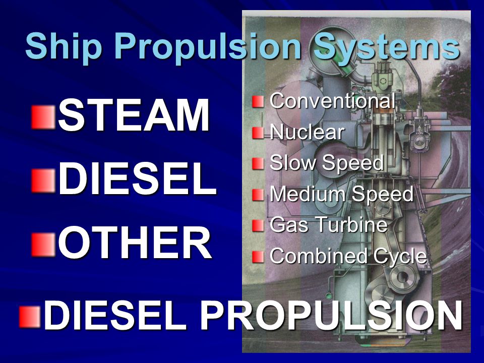
Ship Propulsion Systems STEAMDIESELOTHERConventionalNuclear Slow Speed Medium Speed Gas Turbine Combined Cycle DIESEL PROPULSION

3
DIESEL ENGINE NOMENCLATURE CYLINDER PISTON EXHAUST VALVE INTAKE VALVE FUEL INJECTOR

4
DIESEL ENGINE NOMENCLATURE PISTON TDC (Top Dead Center) BDC BDC (Bottom Dead Center) STROKE BORE
 BDC BDC (Bottom Dead Center) STROKE BORE")
5
THE DIESEL CYCLE 4 EVENTS INTAKE (bring in fresh air charge) COMPRESSION (raise pressure & temperature of charge) POWER (inject and combust fuel – “exploding” gas expands) EXHAUST (remove combustion products)
 COMPRESSION (raise pressure & temperature of charge) POWER (inject and combust fuel – exploding gas expands) EXHAUST (remove combustion products)")
6
THE DIESEL CYCLE FOUR Stroke/Cycle [4 S/C] Engines Each event completed in one stroke INTAKE (TDC BDC) COMPRESSION (BDC TDC) POWER (TDC BDC) EXHAUST (BDC TDC) Cycle completed in TWO revolutions
![THE DIESEL CYCLE FOUR Stroke/Cycle [4 S/C] Engines Each event completed in one stroke INTAKE (TDC BDC) COMPRESSION (BDC TDC) POWER (TDC BDC) EXHAUST (BDC TDC) Cycle completed in TWO revolutions](http://images.slideplayer.com/15/4765287/slides/slide_6.jpg "THE DIESEL CYCLE FOUR Stroke/Cycle [4 S/C] Engines Each event completed in one stroke INTAKE (TDC BDC) COMPRESSION (BDC TDC) POWER (TDC BDC) EXHAUST (BDC TDC) Cycle completed in TWO revolutions")
7
DIESEL CYCLE: Intake STROKE 1

8
DIESEL CYCLE: Compression STROKE 2

9
DIESEL CYCLE: POWER STROKE 3

10
DIESEL CYCLE: Exhaust STROKE 4

11
DIESEL CYCLE: Intake

12
DIESEL CYCLE: Compression

13
DIESEL CYCLE: POWER

14
DIESEL CYCLE: Exhaust

15
DIESEL CYCLE: P-V Diagram TDC COMPRESSION POWER EXHAUST BDC INTAKE Idealized DIESEL CYCLE INTAKE—at atmospheric pressure COMPRESSION—to TDC POWER— –Fuel injected –Constant pressure heating –Expansion EXHAUST—at atmospheric pressure PRESS VOL

16
OTTO CYCLE: P-V Diagram TDC COMPRESSION POWER EXHAUST BDC INTAKE INTAKE—Fuel & air at atmospheric pressure COMPRESSION—to TDC POWER— –Sparkplug ignition –Constant volume heating –Expansion EXHAUST—at atmospheric pressure PRESS VOL Idealized GASOLINE ENGINE

17
DIESEL vs. OTTO CYCLE TDC BDC PRESS VOL DIESEL TDC BDC PRESS VOL OTTO (Gasoline)
")
18
Linear to Rotational Motion CRANK SHAFT WEB CRANK PIN CONNECTING ROD WRIST PIN PISTON RINGS

19
Linear to Rotational Motion TIMING CIRCLE

20
Crank-pin position as timing TIMING CIRCLE INTAKE COMPRESSION POWER FUEL INJECTION Fuel cut-off SCAVENGING INTAKE VALVE OPENS EXHAUST VALVE CLOSES EXHAUST

21
THE DIESEL CYCLE TWO Stroke/Cycle [2 S/C] Engines Each event completed in less than one stroke POWER (TDC before BDC) EXHAUST (before to after BDC) INTAKE (before to after BDC) COMPRESSION (after BDC TDC) Cycle completed in ONE revolution
![THE DIESEL CYCLE TWO Stroke/Cycle [2 S/C] Engines Each event completed in less than one stroke POWER (TDC before BDC) EXHAUST (before to after BDC) INTAKE (before to after BDC) COMPRESSION (after BDC TDC) Cycle completed in ONE revolution](http://images.slideplayer.com/15/4765287/slides/slide_21.jpg "THE DIESEL CYCLE TWO Stroke/Cycle [2 S/C] Engines Each event completed in less than one stroke POWER (TDC before BDC) EXHAUST (before to after BDC) INTAKE (before to after BDC) COMPRESSION (after BDC TDC) Cycle completed in ONE revolution")
22
2 S/C timing COMPRESSION POWER Fuel cut-off EXAUST BEGINS FUEL INJECTION EXHAUST INTAKE SCAVENGING INTAKE BEGINS EXAUST ENDS INTAKE ENDS

23
2 S/C EVENTS

25
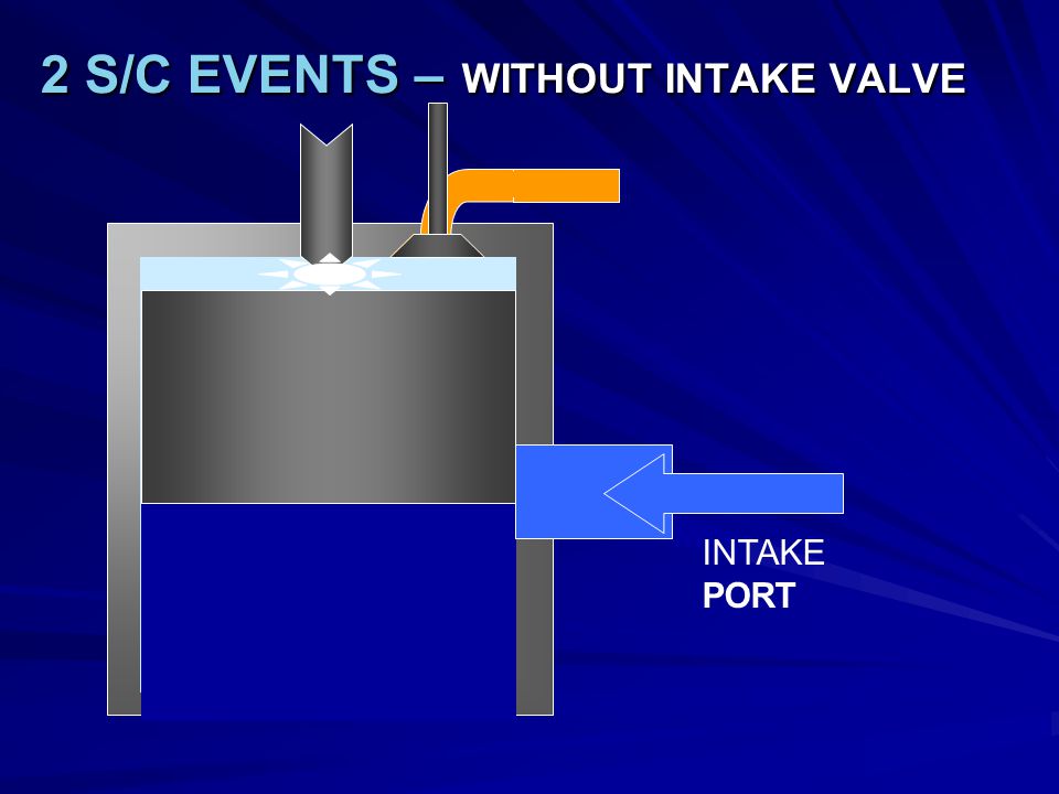
2 S/C EVENTS – WITHOUT INTAKE VALVE INTAKE PORT

26
2 S/C DIESEL CYCLE TDC BDC PRESS VOL Enclosed area: ∫ P dV = Energy delivered per cycle 0 psig MEP MEP—Mean Effective Pressure (“average” pressure during cycle) Equivalent Area (Energy) MEP x STROKE P L A N = HP per Cylinder 33,000 33,000 P– MEP [lbs/in 2 ] L– Stroke [ ft ] A– cylnder area [in 2 ] N-- RPM
![2 S/C DIESEL CYCLE TDC BDC PRESS VOL Enclosed area: ∫ P dV = Energy delivered per cycle 0 psig MEP MEP—Mean Effective Pressure ( average pressure during cycle) Equivalent Area (Energy) MEP x STROKE P L A N = HP per Cylinder 33,000 33,000 P– MEP [lbs/in 2 ] L– Stroke [ ft ] A– cylnder area [in 2 ] N-- RPM](http://images.slideplayer.com/15/4765287/slides/slide_26.jpg "2 S/C DIESEL CYCLE TDC BDC PRESS VOL Enclosed area: ∫ P dV = Energy delivered per cycle 0 psig MEP MEP—Mean Effective Pressure ( average pressure during cycle) Equivalent Area (Energy) MEP x STROKE P L A N = HP per Cylinder 33,000 33,000 P– MEP [lbs/in 2 ] L– Stroke [ ft ] A– cylnder area [in 2 ] N-- RPM")
27
THE DIESEL CYCLE 4 S/C Engines— Each event takes one stroke Cycle completed in two revolutions One power stroke every other revolution) Must have intake AND exhaust valves 2 S/C Engines— Cycle completed in one revolutions (Shorter) power stroke every revolution May have intake and exhaust valves, or –Intake port and exhaust valve, or –Intake and exhaust ports Comprised of INTAKE, COMPRESSION, POWER & EXHAUST EVENTS (fuel injection at beginning of power event)
 Must have intake AND exhaust valves 2 S/C Engines— Cycle completed in one revolutions (Shorter) power stroke every revolution May have intake and exhaust valves, or –Intake port and exhaust valve, or –Intake and exhaust ports Comprised of INTAKE, COMPRESSION, POWER & EXHAUST EVENTS (fuel injection at beginning of power event)")
Similar presentations


 Engine Lab Instructor: M>")
 Patel Vidhi A.>")
 engine To determine the effect of load variation at constant speed.>")


