Download presentation
Presentation is loading. Please wait.

1
Antennas

2
Simple Antennas Isotropic radiator is the simplest antenna mathematically Radiates all the power supplied to it, equally in all directions Theoretical only, can’t be built Useful as a reference: other antennas are often compared with it

3
Half-Wave Dipole Simplest practical antenna
Actual length is typically about 95% of a half wavelength in free space

5
Radiation Resistance Signal radiated into space appears as loss from the antenna Electrically this translates into a resistance For a half-wave dipole fed in the center the radiation resistance is approximately 70 ohms Antennas also have actual resistance due to their conductors

6
Antenna Efficiency

7
Directional Characteristics
All real antennas transmit more power in some directions than in others Two, two-dimensional diagrams are generally used to show radiation patterns Distance from the center represents radiation in different directions Calibration may be in dB relative to max. for that antenna, or relative to isotropic (dBi) or half wave dipole (dBd)
 or half wave dipole (dBd)")
10
Antenna Gain Specifications
dBi means decibels with respect to an isotropic radiator dBd means decibels with respect to an ideal half-wave dipole in its direction of maximum radiation The gain of a dipole is 2.14 dBi

12
dBd/dBi Conversion Gain (dBi) = Gain (dBd) + 2.14 dB
Use dBi in Friis’s Formula Use dBi when it is necessary to find gain as a power ratio compared with isotropic: Gain (ratio) = antilog (dBi/10) Antennas may be specified either way in catalogs, etc. (check!)
 = antilog (dBi/10) Antennas may be specified either way in catalogs, etc. (check!)")
13
Gain and Directivity Directivity is a theoretical value ignoring losses Gain includes losses As a ratio, gain = directivity efficiency Specifications give gain, but computer models often find directivity

14
EIRP and ERP EIRP = effective isotropic radiated power
Equal to the amount of power that would have to be applied to an isotropic radiator to give the same power density at a given point ERP = effective radiated power Equal to the amount of power that would have to be applied to a half-wave dipole, oriented in direction of maximum gain, to give the same power density at a given point

15
EIRP/ERP Conversion EIRP = ERP + 2.14 dB
EIRP is used in all our equations Sometimes government regulations specify ERP for transmitting installations Conversion is easy (see above)
")
16
Dipole Impedance At resonance, Z = 70 resistive if fed in center
Above resonant frequency: inductive Below resonant frequency: capacitive Impedance can be raised by moving feedpoint out towards ends (delta match)
")
17
Dipole Polarization Polarization is same as axis of wire:
Vertical dipole is vertically polarized Horizontal dipole is horizontally polarized

18
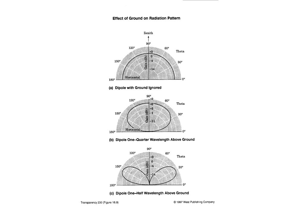
Ground Effects Effect of ground near antenna is important when antenna is within a few wavelengths of ground Very important up to and including HF, usually less important for VHF and up Effect of ground depends on ground characteristics and distance of antenna from ground

19
Reflection from Ground
Phase shift at ground of 180 degrees Perfectly conductive ground would reflect all the power that hits it Real ground is not perfectly conductive conductivity depends largely on moisture content Effect of combinining reflected and direct signals depends on distance from ground

21
Folded Dipole Antenna Same length as half wave dipole
Uses 2 conductors Impedance 4 times that of normal dipole Approximately 300 ohms at resonance Bandwidth is greater than single-conductor dipole

23
Monopole Antenna Vertical
Half the length of a dipole (one-quarter wave approximately) Ground supplies the other half If installed above ground, a ground plane can be used instead For a car antenna, the car is the ground plane Input impedance half that of a dipole, about 35 ohms
 Ground supplies the other half. If installed above ground, a ground plane can be used instead. For a car antenna, the car is the ground plane. Input impedance half that of a dipole, about 35 ohms.")
24
1/4 wave monopole with ground plane for 144 MHz

25
AM Transmitter Tower (The tower is the antenna)
")
27
Loop Antennas Usually small in comparison with wavelength
Used in AM receivers and direction finders May be air-wound or wound on a ferrite rod Bidirectional as shown on next slide

29
5/8 Wavelength Antenna Lower radiation angle and higher impedance than 1/4 wave antenna Can be used without an efficient ground because of the high impedance

30
Discone Antenna Very wide bandwidth
Often used for wideband receiving applications such as scanners

31
Discone antenna for 25-1300 MHz
with whip antenna for transmitting on ham bands

32
Helical Antenna Used to produce circular polarization
Several turns of tubing, usually with a reflector A variant is used for FM broadcasting

33
Antenna Matching Antennas usually are resistive at only one frequency
Even then, resistance may not match feedline impedance Any of the matching schemes discussed previously can be used

34
Antenna Loading Coil When an antenna is too short an inductance can be added to increase its electrical length Loading coils often used at base or center of a vertical monopole The whole antenna can also be wound into a coil This is often done with handheld transceivers

35
Loading Coil

36
Antenna Arrays Simple antennas can be combined to achieve desired directional effects Individual antennas are called elements and the combination is an array

37
Types of Arrays Broadside: maximum radiation at right angles to main axis of antenna End-fire: maximum radiation along the main axis of antenna Phased: all elements connected to source Parasitic: some elements not connected to source They re-radiate power from other elements

38
Yagi-Uda Array Often called Yagi array
Parasitic, end-fire, unidirectional One driven element: dipole or folded dipole One reflector behind driven element and slightly longer One or more directors in front of driveh element and slightly shorter

41
Yagi for 14, 21, 28 MHz Amateur Bands

42
UHF-TV Antenna: Yagi with Corner Reflector

43
Log-Periodic Dipole Array
Multiple driven elements (dipoles) of varying lengths Phased array Unidirectional end-fire Noted for wide bandwidth Often used for TV antennas
 of varying lengths. Phased array. Unidirectional end-fire. Noted for wide bandwidth. Often used for TV antennas.")
45
UHF Yagi with reflector
VHF LPDA VHF/UHF TV Antenna

46
Turnstile Antenna 2 dipoles 90 degrees between them
fed 90 degrees out of phase mounted horizontally Gives an omnidirectional pattern in horizontal plane with horizontal polarization

48
Turnstile Antenna for FM Broadcast Band

49
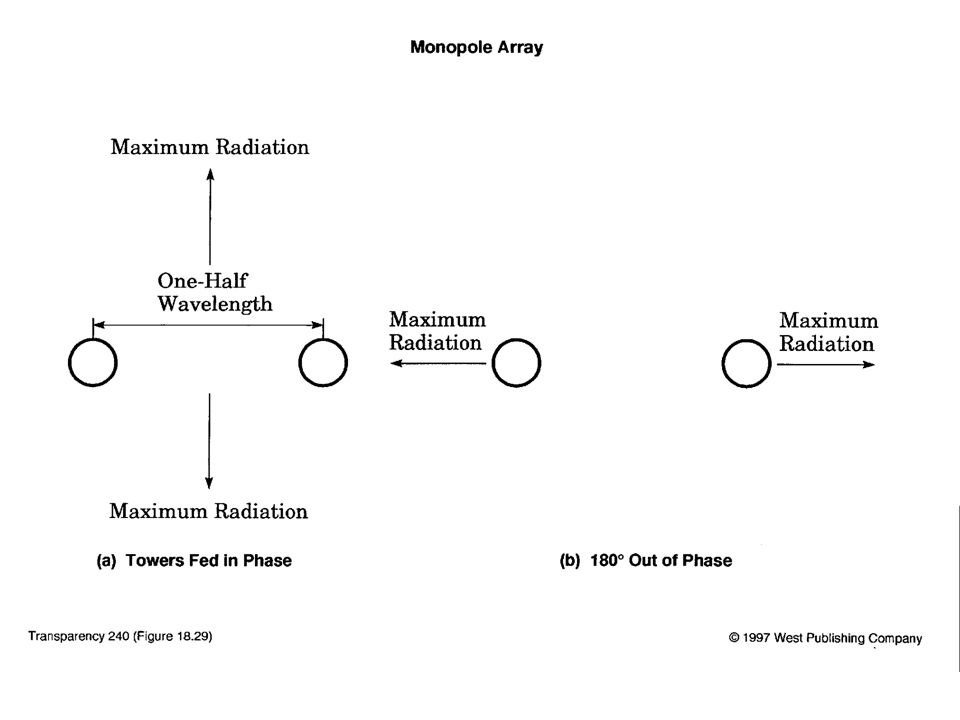
Monopole Array Vertical monopoles can be combined to achieve a variety of horizontal patterns Patterns can be changed by adjusting amplitude and phase of signal applied to each element Not necessary to move elements Useful for AM broadcasting

52
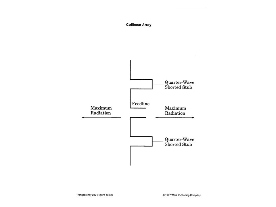
Collinear Array All elements along same axis
Used to provide an omnidirectional horizontal pattern from a vertical antenna Concentrates radiation in horizontal plane

54
Broadside Array Bidirectional Array
Uses Dipoles fed in phase and separated by 1/2 wavelength

57
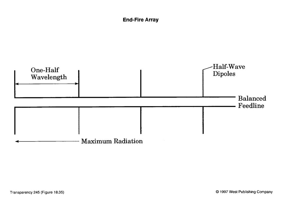
End-Fire Array Similar to broadside array except dipoles are fed 180 degrees out of phase Radiation max. off the ends

59
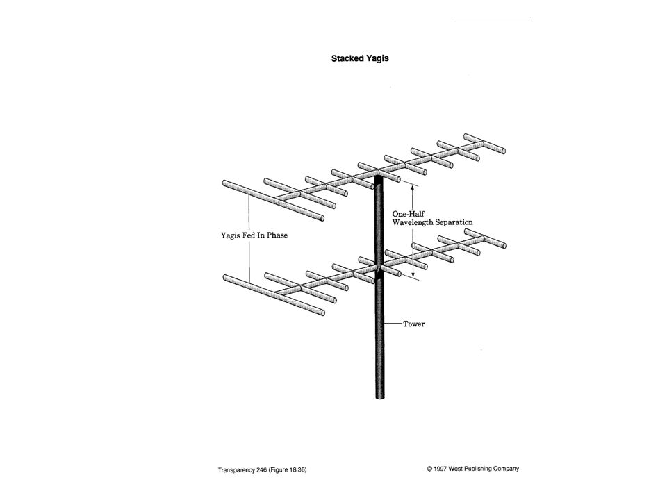
Stacked Yagis Stacking in-phase Yagis with half-wavelength vertical spacing Reduces radiation above and below horizon Increases gain in plane of the antenna

61
Plane Reflector Mount antenna 1/4 wavelength from flat metallic surface Reflected wave and direct wave are in phase along normal to survace Increases radiation in that direction

63
Corner Reflector More focused radiation than plane reflector
Often used with UHF TV antennas

65
UHF-TV Antenna: Yagi with Corner Reflector

66
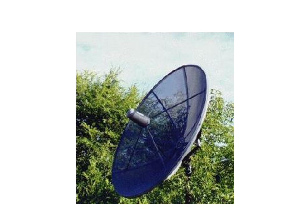
Parabolic Reflector All radiation emitted at focus emerges in a beam parallel to the axis Gives a narrow beam Suitable mainly at microwave frequencies because it must be large compared with the wavelength

70
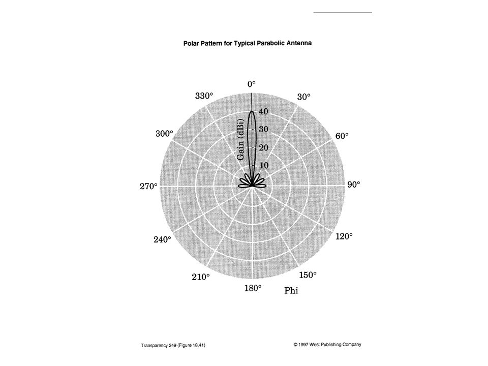
Parabolic Reflector Beamwidth
Beamwidth at half-power points

71
Parabolic Reflector Gain
As a power ratio (not dB) With respect to isotropic
 With respect to isotropic.")
Similar presentations


 Antennas Chelmsford Amateur Radio Society.>")


 slot antennas (half or quarter.>")

![Prof. David R. Jackson Notes 21 Introduction to Antennas Introduction to Antennas ECE 3317 [Chapter 7]](/14/4258526/big_thumb.jpg "Prof. David R. Jackson Notes 21 Introduction to Antennas Introduction to Antennas ECE 3317 [Chapter 7]>")


>")


