Download presentation
Presentation is loading. Please wait.

1
ECE 563 & TCOM 590 Microwave Engineering Planar Transmission Lines: Striplines and Microstrips October 14, 2004

2
Planar Transmission Lines

3
Parallel Plate Waveguide

4
Surface Waves on a Grounded Dielectric Slab 0r0r 00 x z //////////////////////////////////////

5
Surface Waves on a Grounded Dielectric Slab

6
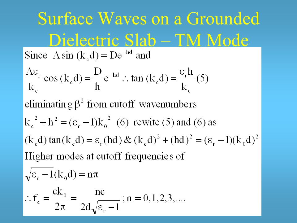
Surface Waves on a Grounded Dielectric Slab – TM Mode

8
TM mode cutoff frequencies

9
Surface Waves on a Grounded Dielectric Slab – TE Modes

10
TE mode cutoff frequencies

11
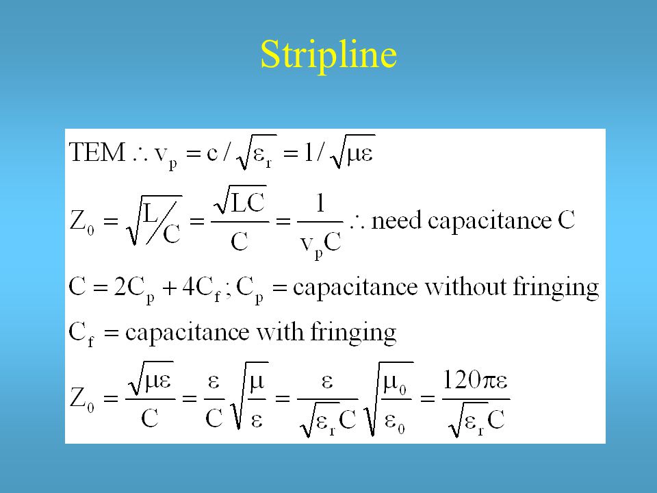
Stripline Triplate transmission line

12
Stripline Advantage (compared to parallel plates) –transverse fields remain in the vicinity of the center conductor between 2 grounded planes –2 conductor line, no lower frequency cutoff: down to f=0, up to cutoff of first TE mode. –Miniaturization

13
Stripline Compared to coax or waveguide –Advantage if Gunn diodes or mixer diodes to be apart of circuit design. –Advantage, large bandwidth, mini-size –Disadvantage- lack of isolation, lower power handling Dominant mode - TEM

14
Stripline

18
Losses

19
Attenuation due to conductor losses (approximate result)
")
20
Planar Transmission Lines

21
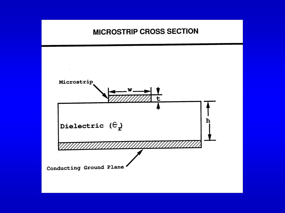
h ////////// t w ////////////////////// Microstrip Lines Popular fabricated by photolithographic processes easily integrated with other passive and active microwave devices convenient, economical; therefore, widespread use Problem radiation and undesired modes by lines at discontinuities

24
Microstrip w t h

25
Microstrip Design

26
Microstrip Design Relationships

27
Normalized Wavelength vs w/h

28
Z 0 and W/d approximation

29
Effects to Dampen Signal Propagation along a Microstrip Signal heats conductor through Ohmic Losses Signal heats substrate which is not lossless Signal leaks away as radiation

30
Ohmic Losses

31
Dielectric Losses

32
Radiation Losses

34
Quality factor

35
Microstrip-line Realization

37
Microstrip Filter Design

38
Microstrip Line Circuit Elements

39
Microwave Transmission

40
Notes on striplines and microstrips ·less bulky than waveguides ·no need for welding and brazing ·planar circuits - 2 dimensional universe ·but high field concentration ·limits power ·breakdown ·heating center condition ·Open structure - radiates

41
Microwave Advances Considerable Interaction –distribution of analog microwave signals via high speed fiber - optic links –optically controlled microwave devices & circuits Photonics Lightwave Techniques –fiber optics –image processing –high speed High Speed Circiuts MMIC’s - Monolithic Integrated Circuits High speed & high frequency

42
Microwave Advances Fiber-optic cables to route microwave signals –reduce size and weight –large bandwidth –immunity to interference –crosstalk isolation –potentially smaller transmission losses –applications feeds for phased array antennas delay lines, cable TV signal signal distribution

43
Millimeter Wave Monolithic Integrated Circuits (MIMIC) Affordable, reliable, reproducible wave and millimeter wave components frequency –tests up to 40 GHz –pulse power goal S-band (3 GHz) to 75 GHz Materials Research –GaAs –High electron mobility transistors (HEMT’s) –CAD –MHDL-Microwave Hardware Descriptive Language
 Affordable, reliable, reproducible wave and millimeter wave components frequency –tests up to 40 GHz –pulse power goal S-band (3 GHz) to 75 GHz Materials Research –GaAs –High electron mobility transistors (HEMT’s) –CAD –MHDL-Microwave Hardware Descriptive Language")
Similar presentations


 through electro-heat.>")


>")