Download presentation
Presentation is loading. Please wait.

1
Manual Transmissions and Transaxles
Chapter 38 Manual Transmissions and Transaxles

2
Transmission Versus Transaxle
RWD vehicles use a transmission A drive shaft links the transmission to the differential and drive axles FWD vehicles use a transaxle Combines transmission gearing, differential, and drive axle connections 4WD vehicles use a transmission and transfer case

3
Typical RWD

4
Typical FWD

5
Typical 4WD

6
Transmission Designs Modern transmissions use four to seven forward speeds Six speeds are most common Fifth and sixth gears are overdrive gears

7
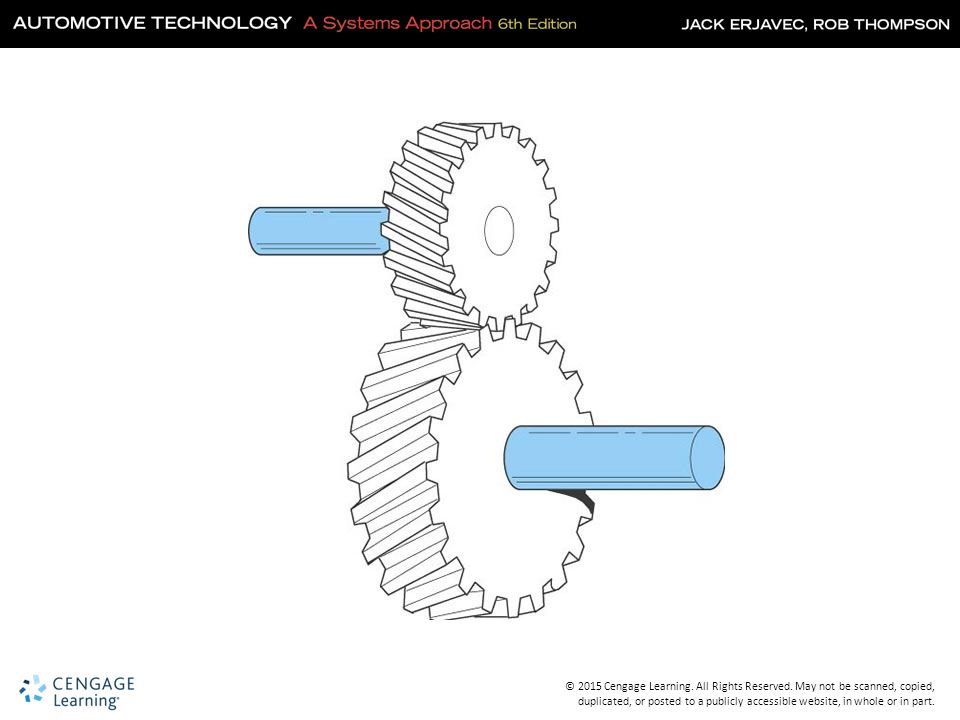
Gears Transmit rotation motion from one parallel shaft to another
The shaft can drive the gear, the gear can drive the shaft, or the gear can be free to turn on the shaft Gears can increase or decrease torque and speed

9
Gear Design Gear pitch refers to the number of teeth per unit of pitch diameter Divide the number of teeth by the pitch diameter Only gears of the same pitch can operate together

10
Gear Pitch

11
Gear Designs (Cont.) Spur Gears Helical Gears Idler Gears
Simplest design, tooth contact causes clicking Helical Gears Can be right or left handed Allows for two or more teeth to mesh at the same time Idler Gears Placed between the drive and driven gears

12
Spur Gears

13
Helical Gears

14
Idler Gear

15
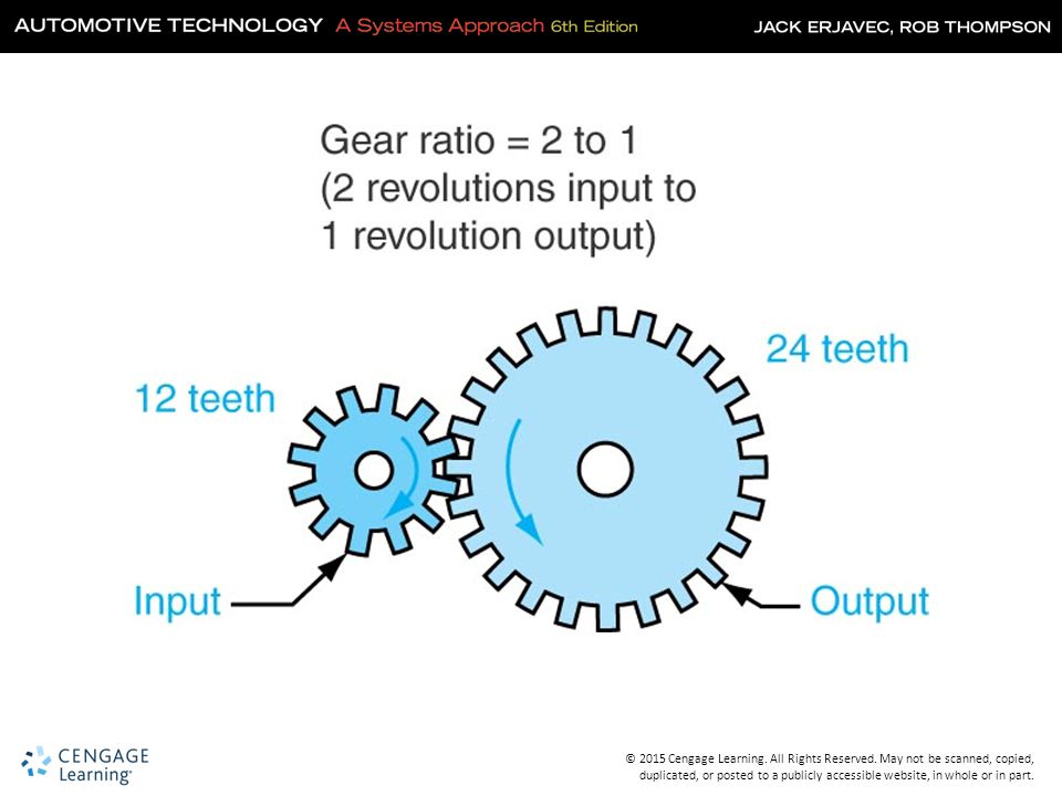
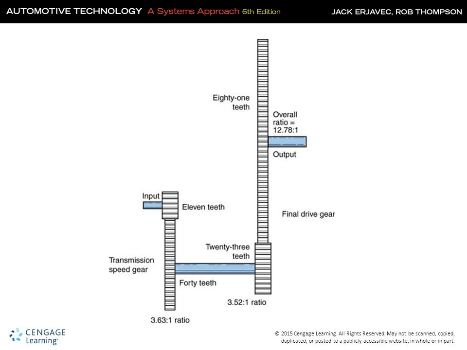
Definition of Gear Ratios
Express the mathematical relationship of one gear to another Express the amount of torque multiplication between gears Tell how many times one gear turns in relation to the other

17
Calculating Transmission Gear Ratios
Calculate the ratio of the first set of gears by dividing the driven (output) gear by the drive (input) gear Do the same for the second set of gears Multiply the answer from the first calculation with the answer from the second calculation driven (a) x driven (b) = drive (a) drive (b)
 gear by the drive (input) gear. Do the same for the second set of gears. Multiply the answer from the first calculation with the answer from the second calculation. driven (a) x driven (b) = drive (a) drive (b)")
19
Knowledge Check Technician A says a gear ratio of 3.5:1 is an overdrive ratio. Technician B says a gear ratio of 0.85:1 is an overdrive ratio. Who is correct? Technician B

20
Transmission and Transaxle Design
Synchromesh Transmissions Gears are constant mesh and collar shifted Collars are equipped with synchronizers Synchronizers eliminate the need to equalize gear speeds before engagement They are used on all current models of cars

21
Transmission Features

22
Transaxle Features

23
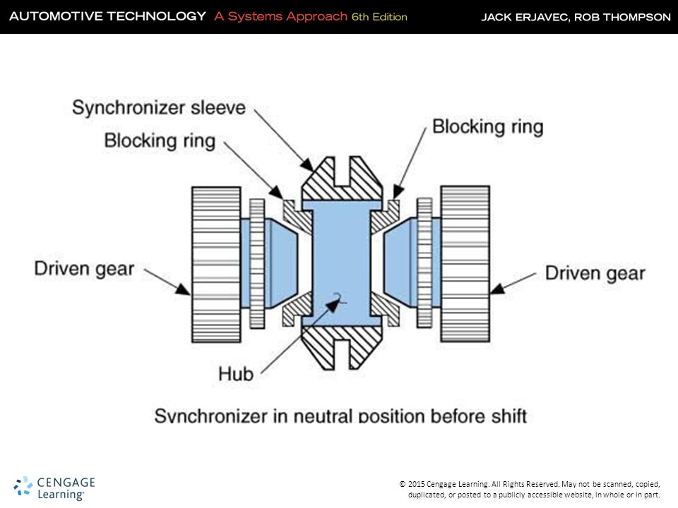
Synchronizers Brings components at different speeds to one synchronized speed Locks the pinion shaft and speed gear May have spur gear teeth cut into outside and act as reverse gear All forward gears synchronized in modern transmissions/transaxles

24
Synchronizer Assembly

25
Block or Cone Synchronizers
Hub – splined to pinion shaft Sleeve – slides onto hub Blocking ring – brass or bronze ring forms the outer half of the gear shoulder cone Inserts or spring-and-ball detent devices

29
Advanced Synchronizer Designs
Multiple cone-type synchronizers Use friction material on both sides of the synchronizer rings Decreases shift effort and increases durability Reduces transmission size since a smaller synchronizer can perform as a larger one

30
Gearshift Mechanisms Shift rails transfer motion from the gearshift to the shift forks The shift forks rest in grooves in the synchronizer sleeves Linkage can be direct or remote and internal or external

31
Direct Internal Linkage

32
Gearshift Linkage Internal-Type External-Type
May be located at the top or side of the transmission Uses a shift rail and detents to select and maintain gear selection External-Type Uses levers and rods that are connected to the outside of the transmission

33
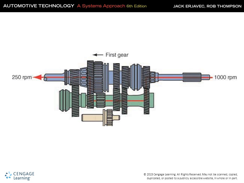
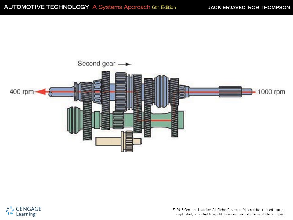
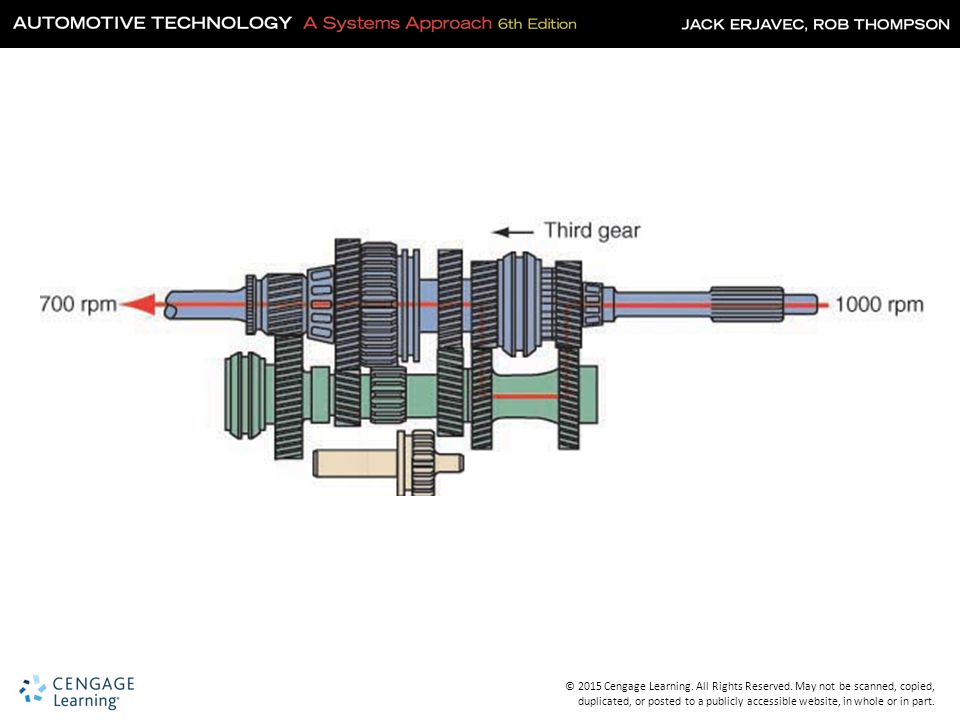
Transmission Power Flow
Neutral The input shaft drives the counter shaft All of the gears on the main shaft rotate The synchronizers are not engaged with any gear No power is transferred to the output shaft

35
Power Flow (Cont.) Forward Gears
The power enters transmission through the input shaft The synchronizer sleeve is engaged with the dog teeth of the selected gear The power is transferred from the input shaft, through the counter shaft, and up to the selected gear The gear drives the output shaft

41
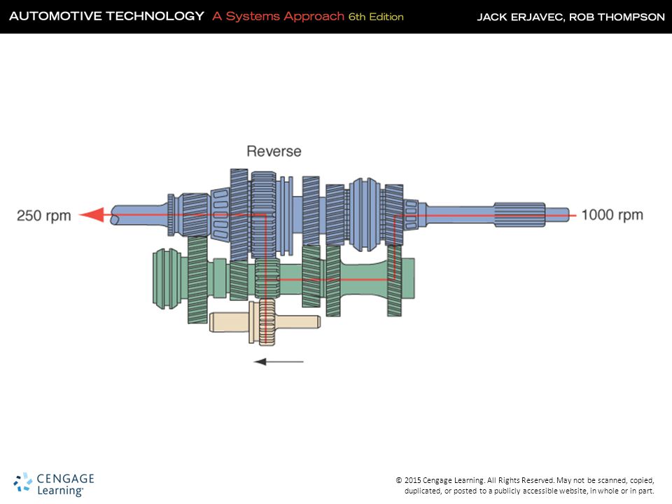
Power Flow (Cont.) Reverse
The power enters transmission through the input shaft The reverse gear synchronizer sleeve is engaged with the reverse gear dog teeth The power is transferred from the input shaft, through the counter shaft, through the reverse idler gear, and up to the reverse gear The reverse gear drives the output shaft in reverse

43
Transaxle Power Flow Neutral
The input shaft is being turned by the engine The synchronizer collars are centered between their gear positions The drive gears are not locked to the output shaft No power is applied to the differential

44
Transaxle Power Flow (Cont.)
Forward Gears The gears on the input shaft are in constant mesh with those on the output shaft The synchronizer hub is splined to the output shaft When a gear is selected, the synchronizer collar engages the hub The power flows from the gear on the input shaft through the selected gear on the output shaft

45
Transaxle Power Flow (Cont.)
")
46
Transaxle Power Flow (Cont.)
Reverse Most transaxles use a sliding reverse gear The shift fork moves the sliding gear in mesh with a gear on the input shaft and one on the output shaft The additional gear causes the output shaft to turn in the direction opposite to the input gear

47
Knowledge Check Which of the gears in a typical RWD transmission is not synchronized? Reverse

48
Differential Action Final drive ring gear driven by the output shaft
Usually does not need to turn 90 degrees Only provides torque multiplication and divide the torque to the axle shafts Provides additional gear reduction beyond the transmission/transaxle called the final drive gear

49
Final Drive Gears and Overall Ratios
All vehicles use a gearset to provide additional gear reduction beyond the transmission This is called the final drive gear Located in the differential housing for transmission-equipped vehicles

50
Rear Differential Action

51
Dual Clutch Transmissions (DCTs)
Becoming very common Can change gears very fast Fuel economy improves Performance improves

52
Input from the Engine May use wet or dry clutches
Dry clutches often used with smaller FWD vehicles Wet clutches often used on larger RWD vehicles

53
Operation A DCT has two separate shafts and sets of gears
One shaft has the even gears, the other shaft the odd gears One clutch is for 1st, 3rd, and 5th gears The other clutch is for 2nd, 4th, and 6th gears

54
Chrysler DCT

55
Electrical Systems Reverse Lamp Switch Vehicle Speed Sensor
Usually on transmission but can be on linkage Vehicle Speed Sensor Sends speed signal to PCM Reverse Lockout Systems Prevents accidental shifting into reverse Shift Blocking Used to improve fuel economy

Similar presentations


 Fundamentals>")


>")


