Download presentation
Presentation is loading. Please wait.

1
Welcome to Electrical Design and Wiring for F.I.R.S.T Championship 2006 Welcome to Electrical Design and Wiring for F.I.R.S.T Championship 2006

2
Presenters Chris Noble - Team 1018 Mentor – Cornerstone Controls Engineer Darrell Noble - Team 71 Mentor – Beatty International Engineer

3
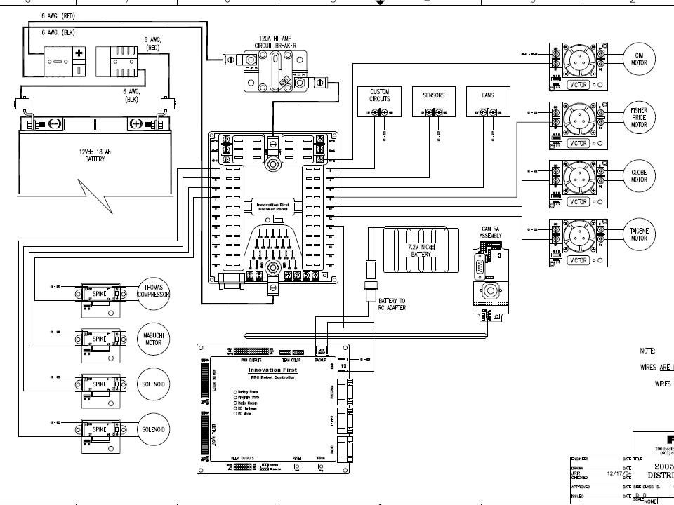
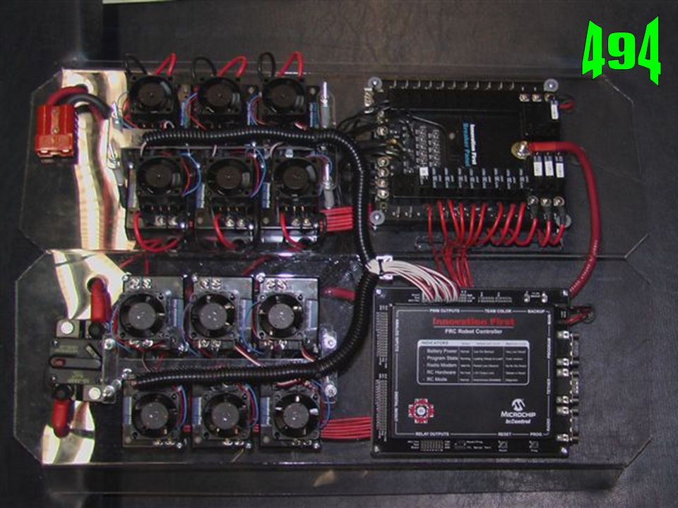
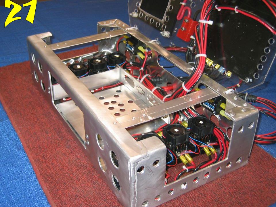
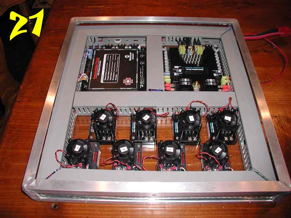
Basic Electronic Theory White and red wire is positive DC voltage Black is negative DC voltage Pressure Switch is an Input ONLY Chassis is not a conductor Install electrical and control wiring so that it is laid out logically and contained with tie wraps, spiral tubing, or shrink tubing Protect your electrical control system from other robots

4
Spike Simply a Relay or On/OFF Switch Controlled by a 5VDC Output from controller through software Has Reverse polarity Components Wired to Spikes: – Air Valves, Compressor – Low current Motors Rated and fused at 20 amps except compressor 20 amp breaker

5
Spike

6
Victors/PWM Victor 884 Pulse Width Modulation Provides Proportional Controls Calibration Break Mode Coast Mode

7
Victors/PWM

8
Circuit Breaker Panel

9
No longer have to guess if breaker is tripped – Status Light Info can be sent back to Operator

11
Wiring Requirements DeviceWire TypeCircuit Breaker Power distribution from battery through 120A Main Circuit Breaker/Disconnect Switch to fuse panels 6 AWG/red & black120A Speed Controllers used with CIM and Fisher-Price Motors 12 AWG/red & black40 A Speed Controllers used with Van Door, or Globe motors 14 AWG/red & black30A Wire size is minimum, larger is also acceptable

12
Features of 2006 Controller C programming language Fast PWM outputs (2ms update) More memory Battery Backup – (FULL only)
 More memory Battery Backup – (FULL only)")
13
Custom Circuits May Not – Directly Control Outputs – Interfere with Operation of Other Robots – Used for Wireless Communications – Connect to programming, tether, competition ports

14
IO for FULL-RC 2006 Interrupt Inputs 6 Digital I/O16, Each can be In or Out Analog Inputs16 (10-bit) Digital Input Sampling Frequency (typical)100KHz Analog Input Access Time10μSec Relay Outputs16 (8 Fwd, 8 Rev) PWM Outputs, Standard refresh every 17mSec 12 PWM Outputs, Fast refresh up to every 2mSec 4
 Digital Input Sampling Frequency (typical)100KHz Analog Input Access Time10μSec Relay Outputs16 (8 Fwd, 8 Rev) PWM Outputs, Standard refresh every 17mSec 12 PWM Outputs, Fast refresh up to every 2mSec 4")
15
Common Features User Microcontroller BrandMicrochip PIC User Microcontroller Type18F8520 User Processor Speed10 MIPS* Variable Space1800 bytes + 255 bytes EE 2 Program Space32K Programming LanguagePIC C Programming ToolsMicrochip MPLAB IDE Serial PortsTTL Serial (115Kb) and RS232 Program (115Kb)
 and RS232 Program (115Kb)")
16
Robot Sensors

17
Robot Sensors Cont.

18
Robot Sensor Cont.

19
CMUcam2 Vision System

20
Clock Rate 75 Mhz. Programmability Reprogrammable via Parallax SX-Key? module and software. User I/O 4 Inputs plus 1 switch input. Servo Outputs 5 User controlled. Servo1 (Pan) and Servo2 (Tilt) can be set for auto tracking colors. Serial Communication via RS-232 or TTL. RS-232 Baud Rate Selection 115200 (default/recommended), others- 57600, 38400, 19200, 9600, 4800, 2400, 1200 baud. Video Output Black & White TV - NTSC standard Servo Power Jumper selectable - Internal or External (comes with jumper installed for Internal selection). Enclosure Use Radio Shack 4"x2"x1" Project Enclosure Box, part number: #270-1802
 and Servo2 (Tilt) can be set for auto tracking colors. Serial Communication via RS-232 or TTL. RS-232 Baud Rate Selection (default/recommended), others , 38400, 19200, 9600, 4800, 2400, 1200 baud. Video Output Black & White TV - NTSC standard Servo Power Jumper selectable - Internal or External (comes with jumper installed for Internal selection). Enclosure Use Radio Shack 4 x2 x1 Project Enclosure Box, part number: #")
21
Sensor Reading Refresh rate is Important Don’t want to miss counts (RPM x Counts/min) -------------------------- = counts/sec 60 1.0 sec ------------- = length of count counts/sec
 = counts/sec sec = length of count counts/sec")
22
Biggest problems of robot electrics Wire coming out of copper connector Breaking Battery terminals off of robot controller Battery falling out Battery coming disconnected Forgot to change battery

23
Common Sources of Trouble PWM light blinking – Normal when no radio – No PWM cable connected – No wire or a broken wire to motor – Balance off on Trim Check connection No Power or Fuse Wired properly Motor Overloaded Thermo protected

24
Trouble Shooting Motor not being driven at all – Check PWM signal light – Check PWM cable – Check power leads from breaker panel – Check power leads to motor – Programming

25
Trouble Shooting Motor moves in one direction only – Use Volt meter to see voltage on output is -12 VDC in one direction 0 VDC neutral +12 VDC in opposite direction If any of these are not Correct – Replace Victor

26
Trouble Shooting Servos not working – Servo power come from back up battery – Plug battery in – Charge battery

27
Always Have the battery SECURED Have the battery connection SECURELY attached in a match Insulate battery terminals

28
Never Never wire with power on !

32
Don’t end up like this!!!

33
More Information FIRST website – Documentation Innovation FIRST – www.innovationfirst.com The FIRST Software Repository – www.frcsoft.com Chief Delphi

34
Questions? Are there any Questions Remember – A neat robot is a safe reliable robot – Read the Rules, then if Not Sure, ask another Team Presentation will be available at www.indianafirst.orgwww.indianafirst.org or www.usfirst.org

Similar presentations


/40GXC(Q) Service Training Sizes 18 and 24K.>")


 Derrick Culver Matt Zenthoefer.>")

 Processing – (Black Box) Output – (Actuators)>")
