Download presentation
Presentation is loading. Please wait.

1
Course Syllabus 1.Color 2.Camera models, camera calibration 3.Advanced image pre-processing Line detection Corner detection Maximally stable extremal regions 4.Mathematical Morphology binary gray-scale skeletonization granulometry morphological segmentation Scale in image processing 5.Wavelet theory in image processing 6.Image Compression 7.Texture 8.Image Registration rigid non-rigid RANSAC

2
References Books: Chapter 11, Image Processing, Analysis, and Machine Vision, Sonka et al Chapter 9, Digital Image Processing, Gonzalez & Woods

3
Topics 1.Basic Morphological concepts 2.Binary Morphological operations Dilation & erosion Hit-or-miss transformation Opening & closing 3.Gray scale morphological operations 4.Some basic morphological operations Boundary extraction Region filling Extraction of connected component Convex hull 5.Skeletonization 6.Granularity 7.Morphological segmentation and watersheds

4
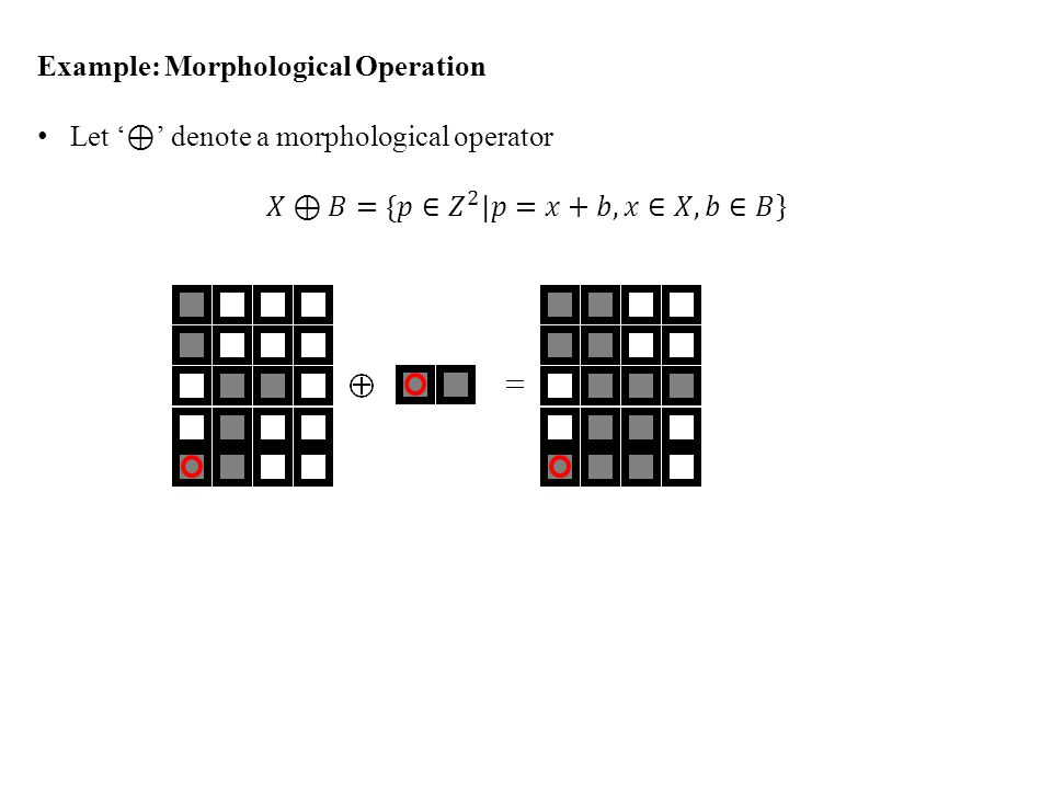
Introduction 1.Morphological operators often take a binary image and a structuring element as input and combine them using a set operator (intersection, union, inclusion, complement). 2.The structuring element is shifted over the image and at each pixel of the image its elements are compared with the set of the underlying pixels. 3.If the two sets of elements match the condition defined by the set operator (e.g. if set of pixels in the structuring element is a subset of the underlying image pixels), the pixel underneath the origin of the structuring element is set to a pre-defined value (0 or 1 for binary images). 4.A morphological operator is therefore defined by its structuring element and the applied set operator. 5.Image pre-processing (noise filtering, shape simplification) 6.Enhancing object structures (skeletonization, thinning, convex hull, object marking) 7.Segmentation of the object from background 8.Quantitative descriptors of objects (area, perimeter, projection, Euler-Poincaré characteristics) binary image structuring element
, the pixel underneath the origin of the structuring element is set to a pre-defined value (0 or 1 for binary images). 4.A morphological operator is therefore defined by its structuring element and the applied set operator. 5.Image pre-processing (noise filtering, shape simplification) 6.Enhancing object structures (skeletonization, thinning, convex hull, object marking) 7.Segmentation of the object from background 8.Quantitative descriptors of objects (area, perimeter, projection, Euler-Poincaré characteristics) binary image structuring element.")
12
Hit-Or-Miss transformation: yet another example

13
Hit-Or-Miss transformation

21
Gray Scale Morphological Operation Basic Morphological concepts Four Morphological principles Binary Morphological operations Dilation & erosion Hit-or-miss transformation Opening & closing Gray scale morphological operations Some basic morphological operations Boundary extraction Region filling Extraction of connected component Convex hull Skeletonization

22
Gray Scale Morphological Operation Support F top surface T[A] Set A
![Gray Scale Morphological Operation Support F top surface T[A] Set A](http://images.slideplayer.com/15/4551033/slides/slide_22.jpg "Gray Scale Morphological Operation Support F top surface T[A] Set A")
23
Gray Scale Morphological Operation A: a subset of n-dimensional Euclidean space, A R n F: support of A Top hat or surface A top surface is essentially a gray scale image f : F R An umbra U(f) of a gray scale image f : F R is the whole subspace below the top surface representing the gray scale image f. Thus,

24
Gray Scale Morphological Operation top surface T[A] umbra Support F
![Gray Scale Morphological Operation top surface T[A] umbra Support F](http://images.slideplayer.com/15/4551033/slides/slide_24.jpg "Gray Scale Morphological Operation top surface T[A] umbra Support F")
25
Gray Scale Morphological Operation top surface T[A]
![Gray Scale Morphological Operation top surface T[A]](http://images.slideplayer.com/15/4551033/slides/slide_25.jpg "Gray Scale Morphological Operation top surface T[A]")
26
Gray Scale Morphological Operation The gray scale dilation between two functions may be defined as the top surface of the dilation of their umbras More computation-friendly definitions Commonly, we consider the structure element k as a binary set. Then the definitions of gray-scale morphological operations simplifies to

27
Morphological Boundary Extraction The boundary of an object A denoted by δ(A) can be obtained by first eroding the object and then subtracting the eroded image from the original image.
 can be obtained by first eroding the object and then subtracting the eroded image from the original image.")
28
Quiz How to extract edges along a given orientation using morphological operations?

29
Morphological noise filtering An opening followed by a closing Or, a closing followed by an opening

30
Morphological noise filtering MATLAB DEMO

31
Morphological Region Filling Task: Given a binary image X and a (seed) point p, fill the region surrounded by the pixels of X and contains p. A: An image where only the boundary pixels are labeled 1 and others are labeled 0 A c : The Complement of A We start with an image X 0 where only the seed point p is 1 and others are 0. Then we repeat the following steps until it converges

32
Morphological Region Filling A AcAc

33
The boundary of an object A denoted by δ(A) can be obtained by first eroding the object and then subtracting the eroded image from the original image. A

34
Morphological Region Filling

36
Homotopic Transformation Homotopic tree r1r2 h1 h2

37
Quitz: Homotopic Transformation What is the relation between an element in the ith and i+1th levels?

38
Skeletonization Skeleton by maximal balls: locii of the centers of maximal balls completely included by the object

39
Skeletonization Matlab Demo HW: Write an algorithm using morphologic operators to retrieve back the portions of the GOOD curves lost during pruning

40
Skeletonization and Pruning Skeletonization preserves both End points Topology Pruning preserves only Topology after skeletonization after pruningafter retrieval

41
Quench function Every location p on the skeleton S(X) of a shape X has an associated radius q X (p) of maximal ball; this function is termed as quench function The set X is recoverable from its skeleton and its quench function
 of a shape X has an associated radius q X (p) of maximal ball; this function is termed as quench function The set X is recoverable from its skeleton and its quench function")
42
Ultimate Erosion The ultimate erosion of a set X, denoted by Ult(X), is the set of regional maxima of the quench functions Morphological reconstruction: Assume two sets A, B such that B A. The reconstruction σ A (B) of the set A is the unions of all connected components of A with nonempty intersection with B. B A
 of the set A is the unions of all connected components of A with nonempty intersection with B. B A.")
43
Ultimate Erosion The ultimate erosion of a set X, denoted by Ult(X), is the set of regional maxima of the quench functions Morphological reconstruction: Assume two sets A, B such that B A. The reconstruction σ A (B) of the set A is the unions of all connected components of A with nonempty intersection with B.
 of the set A is the unions of all connected components of A with nonempty intersection with B..")
44
Convex Hull A set A is said to be convex if the straight line joining any two points within A lies in A. Q: Is an empty set convex? Q: What ar4e the topological properties of a convex set? A convex hull H of a set X is the minimum convex set containing X. The set difference H – X is called the convex deficiency of X.

47
Geodesic Morphological Operations The geodesic distance D X (x,y) between two points x and y w.r.t. a set X is the length of the shortest path between x and y that entirely lies within X. ??

48
Geodesic Balls The geodesic ball B X (p,n) of center p and radius n w.r.t. a set X is a ball constrained by X.

49
Geodesic Operations The geodesic dilation δ X (n) (Y) of the set Y by a geodesic ball of radius n w.r.t. a set X is : The geodesic erosion ε X (n) (Y) of the set Y by a geodesic ball of radius n w.r.t. a set X is :
 (Y) of the set Y by a geodesic ball of radius n w.r.t. a set X is :.")
50
An example What happens if we apply geodesic erosion on X – {p} where p is a point in X?

51
Implementation Issue An efficient solution: select a ball of radius ‘1’ and then define

52
Morphological Reconstruction Assume that we want to reconstruct objects of a given shape from a binary image that was originally obtained by thresholding. All connected components in the input image constitute the set X. However, we are interested only a few connected components marked by a marker set Y.

53
How? Successive geodesic dilations of the set Y inside the bigger set X leads to the reconstruction of connected components of X marked by Y. The geodesic dilation terminates when all connected components of X marked by Y are filled, i.e., an idempotency is reached : This operation is called reconstruction and is denoted by ρ X (Y).
..")
54
Geodesic Influence Zone Let Y, Y 1, Y 2,..Y m denote m marker sets on a bigger set X such that each of Y and Y i s is a subset of X.

55
Reconstruction to Gray-Scale Images This requires the extension of geodesy to gray-scale images. Any increasing transformation defined for binary images can be extended to gray-level images A gray level image I is viewed as a stack of binary images obtained by successive thresholding – this process is called threshold decomposition Threshold decomposition principle

56
Reconstruction to Gray-Scale Images Returning to the reconstruction transformation, binary geodesic reconstruction ρ is an increasing transformation Gray-scale reconstruction: Let J, I be two gray-scale images both over the domain D such that J I, the gray-scale reconstruction ρ I (J) of the image I from J is defined as
 of the image I from J is defined as")
57
Reconstruction to Gray-Scale Images

Similar presentations


 Digital Image Processing (7) 二值形态学 Binary morphology 顾 力栩 上海交通大学 计算机系 2006.4.>")


Image pre-processing.>")


>")

