Download presentation
Presentation is loading. Please wait.

1
Chapter 7 – Serial-Parallel Circuits Introductory Circuit Analysis Robert L. Boylestad

2
Introduction A series-parallel configuration is one that is formed by a combination of series and parallel elements. A complex configuration is one in which none of the elements are in series or parallel.

3
Series-Parallel Networks General approach to circuit analysis: Study the problem in total and make a brief mental sketch of the overall approach you plan to use. Examine each region of the network independently before tying them together in series-parallel combinations. Redraw the network as often as possible with reduced branches and undisturbed unknown quantities to maintain clarity. When you have a solution, check to see that it is reasonable by considering the magnitudes of the energy source and the elements in the network. If it does not seem reasonable, either solve using another approach or check over your work very carefully

4
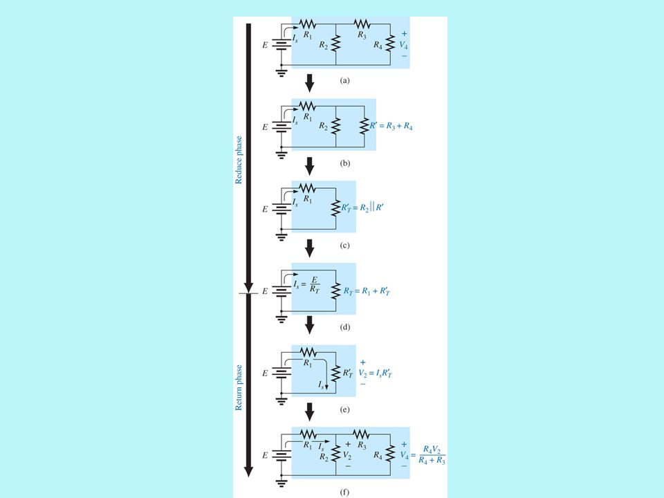
Reduce and Return Approach Reduce: Reduce the circuit to its simplest form across the source and then determine the source current ( I s ). Return: Using the resulting source current ( I s ) to work back to the desired unknown.
 to work back to the desired unknown..")
5
Circuit for reduce and return

7
Block Diagram Approach Network is broken down into combinations of elements. Initially, there will be some concern about identifying series and parallel elements, but that will come with practice. In reverse, the block diagram approach can be used effectively to reduce the apparent complexity of a system by identifying the major series and parallel components of the network.

8
Introducing the block diagram approach.

9
Example

10
Reduced equivalent

11
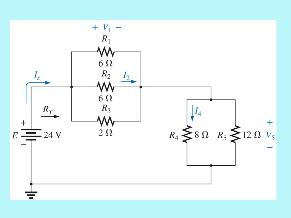
Descriptive Examples Example 1 – Find the current I 4 and the voltage V 2 for the network shown.

13
Descriptive Examples Example 2 – Find the indicated currents and voltages for the network shown.

15
Block diagram

16
Reduced form

17
7.6 – Ladder Networks Repetitive structure that looks like a ladder Method 1 – Calculate the total resistance and resulting source current, and then work back through the ladder until the desired current or voltage is obtained. Method 2 – Assign a letter symbol to the last branch current, and work back through the network to the source, maintaining this assigned current or other current of interest.

18
Ladder network.

19
Potentiometer Loading Unloaded potentiometer – the output voltage is determined by the voltage divider rule, with R T representing the total resistance of the potentiometer.

20
Potentiometer Loading When a load is applied as shown, the output voltage V L is now a function of the magnitude of the load applied since R 1 is not as shown in the previous slide but is instead the parallel combination of R 1 and R L.

21
Loaded potentiometer.

Similar presentations


 LECTURE # 14 BY MOEEN GHIYAS.>")


>")


