Download presentation
Presentation is loading. Please wait.

1
Explaining Vapor Pressure on the Molecular Level Some of the molecules on the surface of a liquid have enough energy to escape the attraction of the bulk liquid. These molecules move into the gas phase. As the number of molecules in the gas phase increases, some of the gas phase molecules strike the surface and return to the liquid. After some time the pressure of the gas will be constant at the vapor pressure. Vapor Pressure

2
Explaining Vapor Pressure on the Molecular Level Vapor Pressure

3
Explaining Vapor Pressure on the Molecular Level Dynamic Equilibrium: the point when as many molecules escape the surface as strike the surface. Vapor pressure is the pressure exerted when the liquid and vapor are in dynamic equilibrium. Volatility, Vapor Pressure, and Temperature If equilibrium is never established then the liquid evaporates. Volatile substances evaporate rapidly. Vapor Pressure

4
Volatility, Vapor Pressure, and Temperature The higher the temperature, the higher the average kinetic energy, the faster the liquid evaporates. Vapor Pressure

5
Volatility, Vapor Pressure, and Temperature Vapor Pressure

7
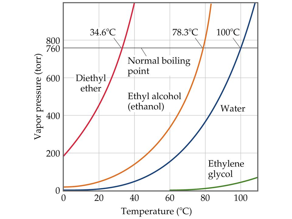
Vapor Pressure and Boiling Point Liquids boil when the external pressure equals the vapor pressure. Temperature of boiling point increases as pressure increases. Vapor Pressure

8
Vapor Pressure and Boiling Point Two ways to get a liquid to boil: increase temperature or decrease pressure. –Pressure cookers operate at high pressure. At high pressure the boiling point of water is higher than at 1 atm. Therefore, there is a higher temperature at which the food is cooked, reducing the cooking time required. Normal boiling point is the boiling point at 760 mmHg (1 atm). Vapor Pressure
. Vapor Pressure.")
9
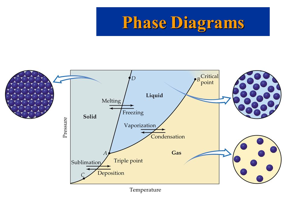
Phase diagram: plot of pressure vs. Temperature summarizing all equilibria between phases. Given a temperature and pressure, phase diagrams tell us which phase will exist. Any temperature and pressure combination not on a curve represents a single phase. Phase Diagrams

10
Features of a phase diagram: –Triple point: temperature and pressure at which all three phases are in equilibrium. –Vapor-pressure curve: generally as pressure increases, temperature increases. –Critical point: critical temperature and pressure for the gas. –Melting point curve: as pressure increases, the solid phase is favored if the solid is more dense than the liquid. –Normal melting point: melting point at 1 atm. Phase Diagrams

12
The Phase Diagrams of H 2 O and CO 2 Phase Diagrams

13
The Phase Diagrams of H 2 O and CO 2 Water: –The melting point curve slopes to the left because ice is less dense than water. –Triple point occurs at 0.0098 C and 4.58 mmHg. –Normal melting (freezing) point is 0 C. –Normal boiling point is 100 C. –Critical point is 374 C and 218 atm. Phase Diagrams
 point is 0 C. –Normal boiling point is 100 C. –Critical point is 374 C and 218 atm. Phase Diagrams.")
14
The Phase Diagrams of H 2 O and CO 2 Carbon Dioxide: –Triple point occurs at -56.4 C and 5.11 atm. –Normal sublimation point is -78.5 C. (At 1 atm CO 2 sublimes it does not melt.) –Critical point occurs at 31.1 C and 73 atm. Phase Diagrams
 –Critical point occurs at 31.1 C and 73 atm. Phase Diagrams.")
15
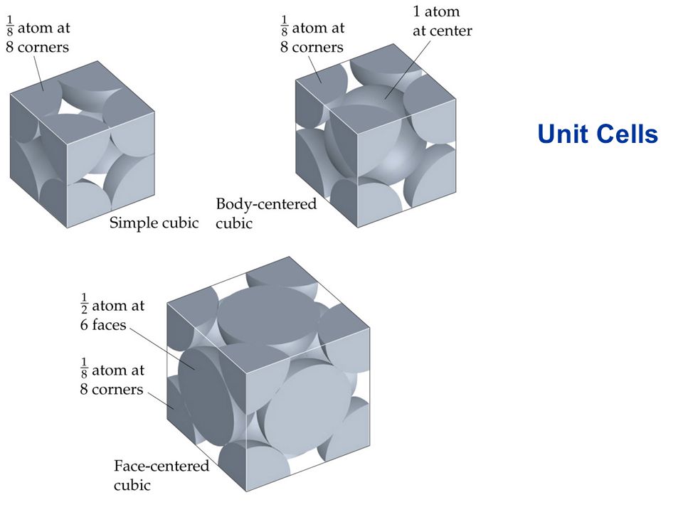
Unit Cells Crystalline solid: well-ordered, definite arrangements of molecules, atoms or ions. Crystals have an ordered, repeated structure. The smallest repeating unit in a crystal is a unit cell. Unit cell is the smallest unit with all the symmetry of the entire crystal. Three-dimensional stacking of unit cells is the crystal lattice. Structures of Solids

16
Unit Cells Structures of Solids

17
Unit Cells Three common types of unit cell. –Primitive cubic, atoms at the corners of a simple cube, each atom shared by 8 unit cells; –Body-centered cubic (bcc), atoms at the corners of a cube plus one in the center of the body of the cube, corner atoms shared by 8 unit cells, center atom completely enclosed in one unit cell; –Face-centered cubic (fcc), atoms at the corners of a cube plus one atom in the center of each face of the cube, corner atoms shared by 8 unit cells, face atoms shared by 2 unit cells. Structures of Solids
, atoms at the corners of a cube plus one in the center of the body of the cube, corner atoms shared by 8 unit cells, center atom completely enclosed in one unit cell; –Face-centered cubic (fcc), atoms at the corners of a cube plus one atom in the center of each face of the cube, corner atoms shared by 8 unit cells, face atoms shared by 2 unit cells. Structures of Solids.")
18
Unit Cells

20
Structures of Solids

21
The Crystal Structure of Sodium Chloride Two equivalent ways of defining unit cell: –Cl - (larger) ions at the corners of the cell, or –Na + (smaller) ions at the corners of the cell. The cation to anion ratio in a unit cell is the same for the crystal. In NaCl each unit cell contains same number of Na + and Cl - ions. Note the unit cell for CaCl 2 needs twice as many Cl - ions as Ca 2+ ions. Structures of Solids

22
The Crystal Structure of Sodium Chloride Structures of Solids

23
The Crystal Structure of Sodium Chloride Structures of Solids

24
Close Packing of Spheres Solids have maximum intermolecular forces. Molecules can be modeled by spheres. Atoms and ions are spheres. Molecular crystals are formed by close packing of the molecules. We rationalize maximum intermolecular force in a crystal by the close packing of spheres. Structures of Solids

25
Close Packing of Spheres When spheres are packed as closely as possible, there are small spaces between adjacent spheres. The spaces are called interstitial holes. A crystal is built up by placing close packed layers of spheres on top of each other. There is only one place for the second layer of spheres. Structures of Solids

26
Close Packing of Spheres There are two choices for the third layer of spheres: –Third layer eclipses the first (ABAB arrangement). This is called hexagonal close packing (hcp); –Third layer is in a different position relative to the first (ABCABC arrangement). This is called cubic close packing (ccp). Structures of Solids
; –Third layer is in a different position relative to the first (ABCABC arrangement). This is called cubic close packing (ccp). Structures of Solids.")
27
Close Packing of Spheres Structures of Solids

28
Close Packing of Spheres Each sphere is surrounded by 12 other spheres (6 in one plane, 3 above and 3 below). Coordination number: the number of spheres directly surrounding a central sphere. Hexagonal and cubic close packing are different from the cubic unit cells. If unequally sized spheres are used, the smaller spheres are placed in the interstitial holes. Structures of Solids

29
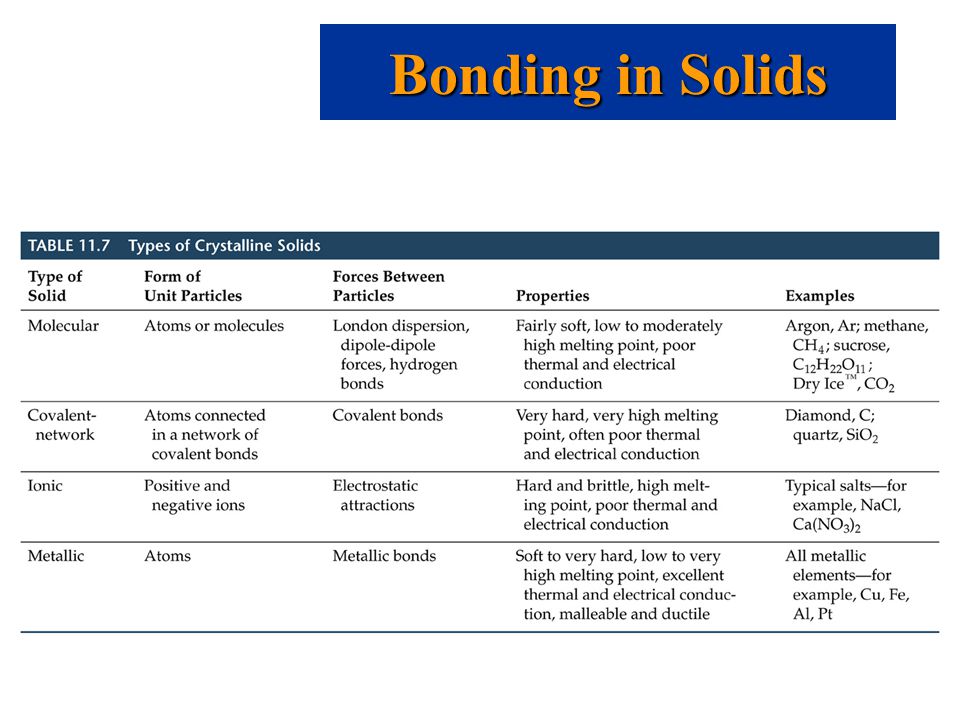
There are four types of solid: – Molecular (formed from molecules) - usually soft with low melting points and poor conductivity. –Covalent network (formed from atoms) - very hard with very high melting points and poor conductivity. –Ions (formed form ions) - hard, brittle, high melting points and poor conductivity. –Metallic (formed from metal atoms) - soft or hard, high melting points, good conductivity, malleable and ductile. Bonding in Solids
 - very hard with very high melting points and poor conductivity. –Ions (formed form ions) - hard, brittle, high melting points and poor conductivity. –Metallic (formed from metal atoms) - soft or hard, high melting points, good conductivity, malleable and ductile. Bonding in Solids.")
31
Molecular Solids Intermolecular forces: dipole-dipole, London dispersion and H-bonds. Weak intermolecular forces give rise to low melting points. Room temperature gases and liquids usually form molecular solids and low temperature. Efficient packing of molecules is important (since they are not regular spheres). Bonding in Solids
. Bonding in Solids.")
32
Covalent-Network Solids Intermolecular forces: dipole-dipole, London dispersion and H-bonds. Atoms held together in large networks. Examples: diamond, graphite, quartz (SiO 2 ), silicon carbide (SiC), and boron nitride (BN). In diamond: –each C atom has a coordination number of 4; each C atom is tetrahedral; there is a three-dimensional array of atoms. –Diamond is hard, and has a high melting point (3550 C). Bonding in Solids
, silicon carbide (SiC), and boron nitride (BN). In diamond: –each C atom has a coordination number of 4; each C atom is tetrahedral; there is a three-dimensional array of atoms. –Diamond is hard, and has a high melting point (3550 C). Bonding in Solids.")
33
Covalent-Network Solids Bonding in Solids

34
Covalent-Network Solids In graphite –each C atom is arranged in a planar hexagonal ring; –layers of interconnected rings are placed on top of each other; –the distance between C atoms is close to benzene (1.42 Å vs. 1.395 Å in benzene); –the distance between layers is large (3.41 Å); –electrons move in delocalized orbitals (good conductor). Bonding in Solids
; –the distance between layers is large (3.41 Å); –electrons move in delocalized orbitals (good conductor). Bonding in Solids.")
35
Ionic Solids Ions (spherical) held together by electrostatic forces of attraction. There are some simple classifications for ionic lattice types. Bonding in Solids

36
Ionic Solids

37
NaCl Structure Each ion has a coordination number of 6. Face-centered cubic lattice. Cation to anion ratio is 1:1. Examples: LiF, KCl, AgCl and CaO. CsCl Structure Cs + has a coordination number of 8. Different from the NaCl structure (Cs + is larger than Na + ). Cation to anion ratio is 1:1. Bonding in Solids
. Cation to anion ratio is 1:1. Bonding in Solids.")
38
Ionic Solids Zinc Blende Structure Typical example ZnS. S 2- ions adopt a fcc arrangement. Zn 2+ ions have a coordination number of 4. The S 2- ions are placed in a tetrahedron around the Zn 2+ ions. Example: CuCl. Bonding in Solids

39
Ionic Solids Fluorite Structure Typical example CaF 2. Ca 2+ ions in a fcc arrangement. There are twice as many F - per Ca 2+ ions in each unit cell. Examples: BaCl 2, PbF 2. Bonding in Solids

40
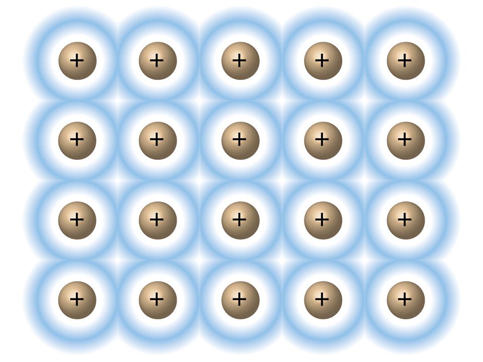
Metallic Solids Metallic solids have metal atoms in hcp, fcc or bcc arrangements. Coordination number for each atom is either 8 or 12. Problem: the bonding is too strong for London dispersion and there are not enough electrons for covalent bonds. Resolution: the metal nuclei float in a sea of electrons. Metals conduct because the electrons are delocalized and are mobile. Bonding in Solids

Similar presentations


 affect the physical properties of a substance? Why does water boil at 100°C and.>")


 molecules. dipole-dipole.>")


