Download presentation
Presentation is loading. Please wait.

1
Drainage Basin Figure 11.3 Christopherson, Elemental Geosystems, Sixth Edition Copyright © 2010 Pearson Education, Inc. 1

2
Drainage Basins Figure 11.5
Christopherson, Elemental Geosystems, Sixth Edition Copyright © 2010 Pearson Education, Inc. 2

5
Drainage Basin System Figure 11.4
Christopherson, Elemental Geosystems, Sixth Edition Copyright © 2010 Pearson Education, Inc. 5

6
Drainage Patterns topographic dome no structural control
folded structures jointing continental glaciation structural dome concentric rock closely spaced faults/monoclines Figure 11.9 Christopherson, Elemental Geosystems, Sixth Edition Copyright © 2010 Pearson Education, Inc. 6

7
Drainage Patterns Random Dendritic f(topography) Parallel Radial
 Parallel Radial")
8
Drainage Patterns Random f(topography) f(lithology) Dendritic Parallel
Radial f(lithology) Trellis Joint trellis
 Trellis. Joint trellis.")
9
Highly Dissected Drainage
how frequently streams occur on the land surface Figure 11.8 Christopherson, Elemental Geosystems, Sixth Edition Copyright © 2010 Pearson Education, Inc. 9

10
Drainage Density Low High Variables Climate Substrate Slope Vegetation
(<5km/km2) low slope low rainfall permeable dense vegetation High (> 500 km/km2) steep slope high rainfall impermeable rock Variables Climate Substrate Slope Vegetation
 low slope. low rainfall. permeable. dense vegetation. High. (> 500 km/km2) steep slope. high rainfall. impermeable rock. Variables. Climate. Substrate. Slope. Vegetation.")
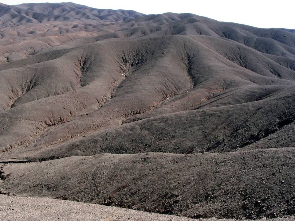
11
Badlands Very high drainage density! Why?

12
Drainage Basins Stream order (Strahler)
Means of classifying basin size 1st order = no tributaries 2nd = two 1st 3rd = two 2nd

13
14 m across 3200 m across Landscapes consist of ridge and valley topography at all scales, but only finest scale reveals the actual valley network and defines the transition between hillslopes and valley fractals exhibit self-similarity; that is similar structure is observed at many scales. With self-similarity, the value of a property depends on the resolution of observation Montgomery and Dietrich, 1992, Science

14
Channel networks are of finite extent.
b b d Channel networks are of finite extent. The spacing of the finest-scale valleys depends on the competition of valley cutting and hillslope eroding processes. Fractal analysis breaks down at the channel-hillslope transition. River basin comprised of network and hillslopes. Hillslopes control production of runoff, sediment, and wood. Network routes these through basin. Spacing or drainage density is another way of saying how well dissected is the landscape? Dissection limited by threshold of channelization.

15
Limitations of Horton-Strahler ordering
Order does not express the intuitive ‘size’ of a catchment very well These look very similar in size, but the left hand net is of order 2, and the right hand net or order 3 Both of these are of order 2, but one looks much ‘bigger’ than the other!

16
Magnitude: an alternative approach (Shreve)
The left hand net has a magnitude of 9, and the right hand has a magnitude of 2 Both of these very similar networks have the same magnitude of 4 Magnitude may give a better idea of the size of the network Shreve explored all the possible network topologies for a given magnitude

17
Magnitude and stream order
Magnitude of a basin is the number of first order or “exterior links” in a catchment. Magnitude correctly emphasizes identifying where the channel begins. Stream order is commonly done on nearly arbitrary network scales, and therefore means little. “Horton’s laws”, which are derived from analysis of stream orders, have no physical meaning. M = 9 N= 2M-1 N= number of links (exterior + interior) For channel head theory, see: Istanbulluoglu et al. JGR 2005 for gully head theory Tucker and Bras, 1998, WRR for theory to landscape evolution
 For channel head theory, see: Istanbulluoglu et al. JGR 2005 for gully head theory. Tucker and Bras, 1998, WRR for theory to landscape evolution.")
19
Watershed Networks Watershed network comprised of
7,100 14,200 21,300 28,400 3,550 Meters Legend nednet <all other values> Order 1 2 3 4 Logan River Network and Watersheds delineated by TauDEM Watershed network comprised of headwater and network systems First and second order streams often comprise 70% of the stream network (Benda et al, 1992) High ecological value Stream networks defined by: Nat’l Hydrography Dataset (1:100,00) Terrain analysis (area, area-slope; area-length thresholds)
 High ecological value. Stream networks defined by: Nat’l Hydrography Dataset (1:100,00) Terrain analysis. (area, area-slope; area-length thresholds)")
20
Effects of low order channels on downstream reaches in the network
Synchronous (or asynchronous) inflows of water, sediment, nutrients, and organic matter create a variety of channel conditions and biological assemblages Connectivity of headwater systems to downstream reaches affects the cumulative and dispersed nature of material transport processes Gomi, et al, Understanding processes and downstream linkages of headwater systems, BioScience, Oct. 2002, vol. 52, no. 10
 inflows of water, sediment, nutrients, and organic matter create a variety of channel conditions and biological assemblages. Connectivity of headwater systems to downstream reaches affects the cumulative and dispersed nature of material transport processes. Gomi, et al, Understanding processes and downstream linkages of headwater systems, BioScience, Oct. 2002, vol. 52, no. 10.")
21
Watershed Delineation by Hand Digitizing
Watershed divide Drainage direction Outlet ArcHydro Page 57

22
River networks and channel morphology
Where do channels begin? Channel network structure

23
Channel Initiation Channel head: the upstream limit of concentrated water flow between banks (Dietrich and Dunne, 1993) a major boundary between hillslopes and channels “pivot point” in sediment transport between diffusive process and incisive process Channel initiation requires runoff Channel initiation occurs by: saturated overland flow seepage erosion shallow landsliding

24
Channel Head Location and Topography
Montgomery and Dietrich, 1989

25
Channel head: threshold transition between hillslope and channel processes
Interplay of channel and hillslope evolution. Channel initiation = f( exposed lithology, vegetation cover, prevailing erosional mechanism) Whatever that might be: SOF, OF channel head location influenced by area and slope
 Whatever that might be: SOF, OF. channel head location influenced by area and slope.")
28
Channel Initiation and Basin Morphometry
Process model for channel initiation by shallow landsliding convergent topography causes colluvium eroded from adjacent hillslopes to accumulate at critical threshold, landsliding occurs exposing underlying material erosion of underlying material by saturation overland flow initiates channel Channel heads controlled by hillslope process rather than network extension Inverse of source basin length ~ drainage density

29
Valleys Hillslopes Dietrich et al., 2003, PIG
channel heads assoc. with a change in sediment transport processes at a critical contributing area. Hillslope sed trans: slope-dependent. Ch. sed trans: slope and discharge-dependent Hillslopes Dietrich et al., 2003, PIG

30
Stock and Dietrich, 2003, WRR

31
Coos Bay, OR Dietrich & Perron, in press,Nature
inflection point is the handoff between landscape disturbances, typically thought of as mass wasting dominated regime to fluvial dominated regime Location of inflection point reflects general environmental controls on ch. initiation (cli, veg) Dietrich & Perron, in press,Nature
 Dietrich & Perron, in press,Nature.")
32
Montgomery and Dietrich, 1992, Science
N. California Oregon Coast Range channeled channel head unchanneled S. California Summary channel heads are defined through a topographically defined ( CA and S) threshold between channeled and unchanneled regions of the landscape threshold behavior Montgomery and Dietrich, 1992, Science
 threshold between channeled and unchanneled regions of the landscape. threshold behavior. Montgomery and Dietrich, 1992, Science.")
33
a= roughness and transport parameters
T= transmissivity q= effective rainfall M=slope F = friction angle q= slope angle a= roughness and transport parameters prevailing erosional mechanism alluded to earlier Example for humid, soil mantled landscape Dietrich et al Geology

34
unchanneled = hillslope
Application of slope- area channel threshold to a digital terrain model channeled unchanneled = hillslope a/b a proxy for contributing area. Mapped channel versus applying slope-area threshold to a DEM For the threshold, no channels observed below this range network topology affects debris flow frequency and slope-area relation transition Observed channel in the field Montgomery and Dietrich, 1992, Science

35
Summary Channel heads typically occur at threshold changes in dominant transport process, and depend both on drainage area and local slope. Channel network structure imparts a transport distance structure (width function) that influences sediment routing.
 that influences sediment routing.")
Similar presentations


 “Stochastic model of erosion– sedimentation processes, based on cellular automata, which mimics the natural variability of climatic.>")


