Download presentation
Presentation is loading. Please wait.

1
Student Launch Project Preliminary Design Review January 10, 2014

2
Team Structure

3
Conceptual 3D Design

4
Vehicle Dimensions

5
Vehicle Materials and Justification MaterialLocationJustification AluminumNose Cone Tip CubeSat Chassis Light Weight Electrically Conductive Phenolic TubingAirframeStrength to Weight Ratio PolycarbonateAirframe LiDAR Payload Bay CubeSat Transparency Strength to Weight Ratio Baltic Birch PlywoodFins Centering rings Bulkheads Strength to Weight Ratio FiberglassNose ConeCommercial Availability Carbon Fiber CoatingNose ConeElectrically Conductive

6
Static Stability Margin Stability Analysis From nose coneWith Booster SectionWithout Booster Section Center of Pressure83.2683”61.4343” Center of Gravity73.1953”50.5965” Static Stability Margin1.631.75 Rail Size/Length1.5” (1515) / 96”
 / 96")
7
Risk Assessment Team safety briefings Consult mentor and industry experts Verify design with calculations and RockSim analysis Identify potential hazards for construction and launch Follow launch checklists and guidelines NAR High Power Rocket Safety Code Comply with federal, state, and local laws Plan for Vehicle Safety Verification

8
Baseline Motor Selection MotorBrand Engine CodeDiameterLengthBurn TimeImpulseThrust BoosterCesaroniJ240 RL54 mm9.2913 in3.35 s 808.959 Ns241.624 N MainCesaroniL61098mm16.8110 in8.13s 4842.188 Ns595.595 N SustainerCesaroni L3150 Vmax98mm15.5118 in1.57 s 4806.279 Ns 3063.279 N

9
Thrust-to-Weight Ratio and Rail Exit Ascent Analysis With Booster SectionWithout Booster Section Rail exit velocity (ft/s)69.1686- Max velocity (ft/s)752.02621531.9175 Max Mach number0.671.41 Max acceleration (ft/s 2 )238.1190802.79 Peak altitude (ft)500018500 Thrust-to-Weight Ratio5.63:124.43:1
 Max velocity (ft/s) Max Mach number Max acceleration (ft/s 2 ) Peak altitude (ft) Thrust-to-Weight Ratio5.63:124.43:1")
10
Launch Vehicle Verification Verification of the design requirements will be completed for the structure, recovery, and propulsion subsystems Analysis using computer simulations or calculations Testing hardware components Static testing before launch Inventory of all structural equipment Inspect fins for damage and stability Inspect detachable components for secure attachment Inspect rail buttons for secure attachment Inspect all parallel boosters and main motors

11
Recovery System ParameterDrogueMainParallelBooster Diameter62”90”20”55” Deployment Altitude18500’1200’4445’5000’ Velocity at Deployment (f/s) 0.872839.1800418.2604 Decent Rate (ft/s)1518.61222.421.42 Kinetic Energy (ft- lbs) 15757.8349.13 Recovery Harness Material 1” Tubular Nylon Harness Length (ft)20’30’3’10’
 Decent Rate (ft/s) Kinetic Energy (ft- lbs) Recovery Harness Material 1 Tubular Nylon Harness Length (ft)20’30’3’10’")
12
Recovery System Electronics/Ejection Altimeter Make/Model 2x Missile Works mini RRC2 Redundancy Plan Each altimeter has an independent drogue/main charge. Redundant altimeter set to deploy 2 s after apogee and 2 s after 1200 ft. Pad Stay Time (Launch Configuration) > 4 hours Rocket Locators Mini Global GPS Tracker, Adafruit Ultimate GPS v3, USGlobalSat EM-406A Black Powder Mass Drogue Parachute 4.752 g Black Powder Mass Main Parachute 7.56 g
 > 4 hours Rocket Locators Mini Global GPS Tracker, Adafruit Ultimate GPS v3, USGlobalSat EM-406A Black Powder Mass Drogue Parachute g Black Powder Mass Main Parachute 7.56 g.")
13
Recovery System Verification ComponentVerification Method Attachment pointsExpected loads ParachutesSimulated masses Ejection chargesGround tested for adequate force Parallel Boosters Ejection MethodMotor Eject Booster Locators Mini Global GPS Tracker Booster Section Altimeter Make/Model Adept Rocketry DCS1 Deployment Controller Altimeter Pad Stay Time (Launch Configuration) > 4 hours Rocket Locators Mini Global GPS Tracker Black Powder Mass Booster Section Parachute 1.404 g
 > 4 hours Rocket Locators Mini Global GPS Tracker Black Powder Mass Booster Section Parachute g")
14
LiDAR Hazard Detection System

15
Rotating Mirrors Processing Subsystem Ranging Subsystem Ground Station

16
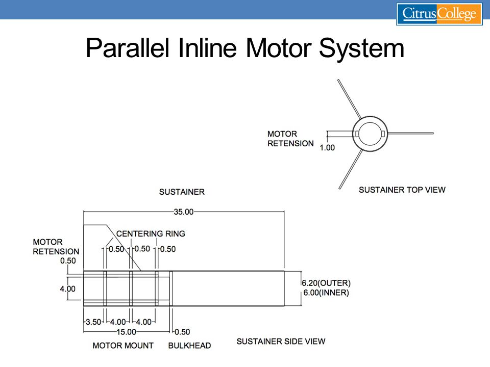
Parallel Inline Motor System

18
Parallel Stage Inline Stage Electronics

19
Tesseract

20
Electrometer CubeSat Ground Station

21
Payload Verification Complete all ground testing pertinent to payload functionality. Set all control data. Ensure proper wiring for all electrical components before launch. Inspect all payload bays and detachment points for structural integrity prior to launch.

22
Questions?

Similar presentations


 Diameter: 6 in Fin Semi-Span: 6 in.>")


