Download presentation
Presentation is loading. Please wait.

2
Apiwat Muttamara Polymer and Plastics Manufacturing Polymer and Plastics Manufacturing

3
Outline Polymer Equipment and process steps Design for manufacturing, tooling and defects

4
Materials Solid materials metals ceramics Plastics thermoplastics thermosetts elastomers Plastic: Greek, plastikos, means to form or mold

5
Automotive Plastics and Composites Use Exterior –doors –hoods –fenders –bumper covers (most cars have soft fascia) Interior –instrument panels, door trim, seats, consoles Engine –valve covers, intake manifolds, fluid containers, etc.
 Interior –instrument panels, door trim, seats, consoles Engine –valve covers, intake manifolds, fluid containers, etc.")
6
Plastics History

7
Thermoplastics & Thermosets amorphous or semicrystalline cross-linked (3D network)
")
8
THERMOPLASTIC, THERMOSET: Thermoplastics are resins that can be reground after molding, and molded again. Thermoplastic are often compared to Wax. Thermosets can be molded once only; they tend to be denser materials for special purposes, thermosets are often compared to an egg; once the egg is hard boiled it can't be returned to a liquid and recooked as sunny side up.

9
Polymer poly = many mer = part A polymer is a long chain molecule that is composed of a large number of repeating units of identical structure. While the term polymer in popular usage suggests "plastic",plastic

10
Petroleum These different hydrocarbons have different boiling points, which means they can be separated by distillationhydrocarbonsboiling points distillation

11
Polymerization of Polyethylene n = degree of polymerization

14
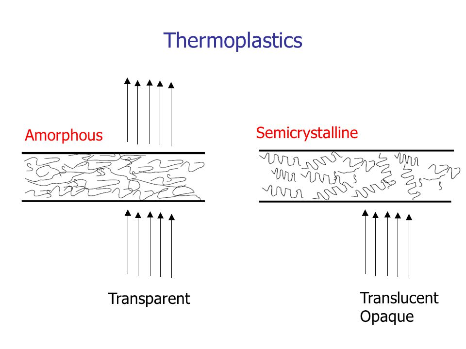
Thermoplastics Amorphous Transparent Semicrystalline Translucent Opaque

15
Fringed-micelle model of semicrystalline polymers โมเลกุลมีการจัดเรียงโดย ส่วนหนึ่งเรียงตัวอย่าง ไม่ เป็นระเบียบ (amorphous region) และบางส่วนจัดเรียงอย่าง เป็น ระเบียบ (crystalline region) SEMI-CRYSTALLINE POLYMERS ( พอลิเมอร์กึ่งผลึก )
 และบางส่วนจัดเรียงอย่าง เป็น ระเบียบ (crystalline region) SEMI-CRYSTALLINE POLYMERS ( พอลิเมอร์กึ่งผลึก )")
16
YIELD AND TENSILE STRENGTHS OF PLASTIC POLYMER Specimen breaks YIELD Yield stress ( y ) ความเค้นที่พบการเสียรูปพลาสติก (plastic deformation) Tensile strength (TS) ( สำหรับพอลิเมอร์ ) ความเค้นที่ชิ้นงานแตกหัก ** ( ทั่วไป ) ความเค้นสูงสุดบนกราฟ engineering stress-strain
 ความเค้นที่พบการเสียรูปพลาสติก (plastic deformation) Tensile strength (TS) ( สำหรับพอลิเมอร์ ) ความเค้นที่ชิ้นงานแตกหัก ** ( ทั่วไป ) ความเค้นสูงสุดบนกราฟ engineering stress-strain")
17
STAGES OF DEFORMATION OF A SEMI-CRYSTALLINE POLYMER MACROSCOPIC DEFORMATION Note: พบลักษณะคอดกิ่วภายใต้การดึง เรียกว่า Necking necking

18
STAGES IN DEFORMATION OF A SEMICRYSTALLINE POLYMER Before deformation Elongation of amorphous tie chains Tilting of lamellar chain folds Separation of crystalline block segment Orientation of block segments

19
Thermoplastic and Thermosetting Polymers (crosslinked and network polymers) vulcanized rubbers, Polyurethane Epoxy, Polyester PVC, PSPE, PP Polyetherimide Polysulfone Polyphenylene Sulfide (PPS) ABS, PC PPE, Acrylic PPE/Nylon PC/PBT ABS/PC Acetal PBT, PET Polyamide (Nylon)
 vulcanized rubbers, Polyurethane Epoxy, Polyester PVC, PSPE, PP Polyetherimide Polysulfone Polyphenylene Sulfide (PPS) ABS, PC PPE, Acrylic PPE/Nylon PC/PBT ABS/PC Acetal PBT, PET Polyamide (Nylon)")
20
Phenolics (named Bakelite by Leo Bakeland) - Resin could be shaped and hardened with heat - Phenol and formaldehyde reaction after heat - Replacement for shellac, natural plastic (1907) Early Plastics Nylon66 - W. H. Carothers of DuPont (1920’s) PVC - W. Semon of B.F. Goodrich (1929)
 PVC - W. Semon of B.F. Goodrich (1929).")
21
Codes for plastics Recycling of Plastics

22
Polymer Additives A polymer contains several additives to aid during processing, add color, or enhance the mechanical properties. Fillers reinforcing fillers improve mechanical properties non-reinforcing fillers (or extenders) reduce cost Plasticizers reduce Tg therefore the flexibility is improved Stabilizers prevent degradation of polymer from heat or UV Colorants add color to polymers Flame Retardants enhance the flammability resistance
 reduce cost Plasticizers reduce Tg therefore the flexibility is improved Stabilizers prevent degradation of polymer from heat or UV Colorants add color to polymers Flame Retardants enhance the flammability resistance.")
23
Amorphous Commodity Thermoplastics Key Characteristics Low cost Low temperature resistance Low strength Good dimensional stability Bonds well Typically transparent

24
Amorphous Commodity Thermoplastics Materials Polymethyl methacrylate (PMMA) Polystyrene (PS) Acrylonitrile butadiene styrene (ABS) Polyvinyl chloride (PVC) Polycarbonate (PC)
 Polystyrene (PS) Acrylonitrile butadiene styrene (ABS) Polyvinyl chloride (PVC) Polycarbonate (PC)")
25
Acrylic (PMMA) Strengths Availability of all ranges of optical transparency, including opacity Rigidity Surface hardness Half the weight of glass Heat resistance Low impact strength
 Strengths Availability of all ranges of optical transparency, including opacity Rigidity Surface hardness Half the weight of glass Heat resistance Low impact strength")
26
Acrylic (PMMA) Protective glazing Windows Toys Point of purchase (POP) displays
 Protective glazing Windows Toys Point of purchase (POP) displays")
27
Polystyrene (PS) Low impact resistance Brittle after UV exposure Cannot be used at elevated temperatures Mechanical stress
 Low impact resistance Brittle after UV exposure Cannot be used at elevated temperatures Mechanical stress")
28
Acrylonitrile Butadiene Styrene (ABS) Good impact resistance Easily formable Many different formulations EX. Computer housings Consumer electronics Automotive

29
Polyvinyl Chloride (PVC) Strengths Low cost Good chemical resistance Versatile Naturally UV resistant Good strength Packaging
 Strengths Low cost Good chemical resistance Versatile Naturally UV resistant Good strength Packaging")
30
Polycarbonate (PC) Vandal resistant windows Machine guards Outdoor signs Sky lights Backboards Bike, roller blading protective wear Excellent toughness Excellent strength
 Vandal resistant windows Machine guards Outdoor signs Sky lights Backboards Bike, roller blading protective wear Excellent toughness Excellent strength")
31
Semi-Crystalline Commodity Plastics Polyethylene (PE) –High density polyethylene (HDPE) –Low density polyethylene (LDPE), (LLDPE) Polypropylene (PP) Polyethylene Terephthalate (PET)
 –High density polyethylene (HDPE) –Low density polyethylene (LDPE), (LLDPE) Polypropylene (PP) Polyethylene Terephthalate (PET)")
32
Low Density Polyethylene (LDPE) High Density Polyethylene (HDPE) Films Industrial trash bags Liners Shipping bags Marine industry Playgrounds Bathrooms Pipe Automotive
 High Density Polyethylene (HDPE) Films Industrial trash bags Liners Shipping bags Marine industry Playgrounds Bathrooms Pipe Automotive")
33
Polypropylenes (PP) Applications Packaging Automotive Consumer/durable goods Vacuum formed parts Fiber/carpet
 Applications Packaging Automotive Consumer/durable goods Vacuum formed parts Fiber/carpet")
34
Polyethylene Terephthalate (PET) High dimensional stability under heat High stiffness and hardness Good bearing strength Good electrical properties Good resistance to chemicals Good stress-cracking resistance Excellent flow characteristics
 High dimensional stability under heat High stiffness and hardness Good bearing strength Good electrical properties Good resistance to chemicals Good stress-cracking resistance Excellent flow characteristics")
35
Plastic Processes Thermoplastic –Extrusion –Blow mold –Rotational Molding –Injection –Thermo forming –Injection molding Thermosetting –Compression –Transfer

36
Plastics Processing: Compression and Transfer Molding used mostly for thermosetting polymers mold is heated and closed using pressure plastic flows to fills the cavity flash must be trimmed by finishing dishes, handles for cooking pots skis, housing for high-voltage switches some rubber parts like shoe soles and even composites such as fiber-reinforced parts

37
Plastics Processing: Compression and Transfer Molding compression molding transfer molding (more complex shapes)
")
38
Plastics Processing: Extrusion

39
Plastics Processing: Blow molding

40
The process generally makes use of polyethylene powders, other powders, and liquids. However, nylon, elastomers, fluoropolymers, and polypropylene can also be used Rotational Molding

41
Sample Rotational molding, otherwise known as rotomolding or rotational casting, is a thermoplastic processing method for producing simple to complex, leak-proof hollow parts that can be filled with foam.

42
Plastics Processing : Thermoforming Sheet of plastic Heated (soft) Molded using a shaped die
 Molded using a shaped die")
43
Vacuum thermoforming

44
Thermoforming Heater Plastics sheet Clamping Vacuum * ** * Source: R. Ogorkiewicz, “Engineering Properties of Thermoplastics.”; ** http://www.arrem.com/designguide/dgprocesscap.htmhttp://www.arrem.com/designguide/dgprocesscap.htm Thin corner

45
Plastics Processing: Injection Molding - Probably the most common, most important, most economical process

46
Injection Molding Machine

47
Steps of Injection Molding – Mold closing

48
Mold filling

49
Packing, holding, cooling

50
Mold opening, part removal Ejector pins

51
Mold Structure

52
Mold Structure - Cavity and core

53
Mold Structure: Parting line A dividing line between a cavity plate and a core plate of a mold. - Make a parting line on a flat or simple-curved surface so that flash cannot be generated. - Venting gas or air.

54
Two plate mold One parting line

55
Three plate mold Two parting lines

56
Melt Delivery Sprue A sprue is a channel through which to transfer molten plastics injected from the injector nozzle into the mold. Runner A runner is a channel that guides molten plastics into the cavity of a mold. Gate A gate is an entrance through which molten plastics enters the cavity.

57
Gate -Delivers the flow of molten plastics. -Quickly cools and solidifies to avoid backflow after molten plastics has filled up in the cavity. -Easy cutting from a runner -Location is important to balance flow and orientation and to avoid defects.

58
Runner cross section Runner cross section that minimizes liquid resistance and temperature reduction when molten plastics flows into the cavity. - Too big - Longer cooling time, more material, cost - Too small - short shot, sink mark, bad quality - Too long - pressure drop, waste, cooling Hot runner, runnerless mold

59
Runner balancing Balanced Not balanced

60
Defects Molding defects are caused by related and complicated reasons as follows: * Malfunctions of molding machine * Inappropriate molding conditions * Flaws in product and mold design * Improper Selection of molding material

61
Weldline This is a phenomenon where a thin line is created when different flows of molten plastics in a mold cavity meet and remain undissolved. It is a boundary between flows caused by incomplete dissolution of molten plastics. It often develops around the far edge of the gate. Cause Low temperature of the mold causes incomplete dissolution of the molten plastics. Solution Increase injection speed and raise the mold temperature. Lower the molten plastics temperature and increase the injection pressure. Change the gate position and the flow of molten plastics. Change the gate position to prevent development of weldline.

62
Flashes Flashes develop at the mold parting line or ejector pin installation point. It is a phenomenon where molten polymer smears out and sticks to the gap. Cause Poor quality of the mold. The molten polymer has too low viscosity. Injection pressure is too high, or clamping force is too weak. Solution Avoiding excessive difference in thickness is most effective. Slow down the injection speed. Apply well-balanced pressure to the mold to get consistent clamping force, or increase the clamping force. Enhance the surface quality of the parting lines, ejector pins and holes.

63
Short shot This is the phenomenon where molten plastics does not fill the mold cavity completely. and the portion of parts becomes incomplete shape. Cause The shot volume or injection pressure is not sufficient. Injection speed is so slow that the molten plastics becomes solid before it flows to the end of the mold. Solution Apply higher injection pressure. Install air vent or degassing device. Change the shape of the mold or gate position for better flow of the plastics.

64
Warpage This deformation appears when the part is removed from the mold and pressure is released. Cause Uneven shrinkage due to the mold temperature difference (surface temperature difference at cavity and core), and the thickness difference in the part. Injection pressure was too low and insufficient packing. Solution Take a longer cooling time and lower the ejection speed. Adjust the ejector pin position or enlarge the draft angle. Examine the part thickness or dimension. Balance cooling lines. Increase packing pressure.
, and the thickness difference in the part. Injection pressure was too low and insufficient packing. Solution Take a longer cooling time and lower the ejection speed. Adjust the ejector pin position or enlarge the draft angle. Examine the part thickness or dimension. Balance cooling lines. Increase packing pressure..")
65
Sink marks -Equal cooling from the surface -Secondary flow -Collapsed surface Sink Mark tsts t t s < t

66
CAE (computer aided engineering) Process simulation Material data base CAD MOLDFLOW C-Flow
 Process simulation Material data base CAD MOLDFLOW C-Flow")
67
Considerations in design of injection molded parts Guideline (3) gate location determines weld lines weld lines * Source: http://www.idsa-mp.org/proc/plastic/injection/injection_design_7.htmhttp://www.idsa-mp.org/proc/plastic/injection/injection_design_7.htm
 gate location determines weld lines weld lines * Source:")
68
Injection Molding: molds with moving cores and side-action cams - If the geometry of the part has undercuts [definition ?]
![Injection Molding: molds with moving cores and side-action cams - If the geometry of the part has undercuts [definition ]](http://images.slideplayer.com/14/4378540/slides/slide_68.jpg "Injection Molding: molds with moving cores and side-action cams - If the geometry of the part has undercuts [definition ]")
69
Mold Structure: Undercut, Slide core

70
Designing injection molds: typical features [source: www.idsa-mp.org]

71
Designing injection molds: typical features

Similar presentations


 Date: April 14, 2000 Slide:1 Environmentally Conscious Design & Manufacturing Class 17: Plastics.>")


>")


