Download presentation
Presentation is loading. Please wait.

1
Basic Electricity

2
Connecting Satellites and Electronics All you need to be an inventor is a good imagination and a pile of junk. -Thomas Edison

3
To understand electronics we must review basic electricity. What is Electricity? Everything is made of atoms There are 118 elements, an atom is a single part of an element Atom consists of electrons, protons, and neutrons

4
Electrons (- charge) are attracted to protons (+ charge), this holds the atom together Some materials have strong attraction and refuse to loss electrons, these are called insulators (air, glass, rubber, most plastics) Some materials have weak attractions and allow electrons to be lost, these are called conductors (copper, silver, gold, aluminum) Electrons can be made to move from one atom to another, this is called a current of electricity.
 are attracted to protons (+ charge), this holds the atom together Some materials have strong attraction and refuse to loss electrons, these are called insulators (air, glass, rubber, most plastics) Some materials have weak attractions and allow electrons to be lost, these are called conductors (copper, silver, gold, aluminum) Electrons can be made to move from one atom to another, this is called a current of electricity.")
5
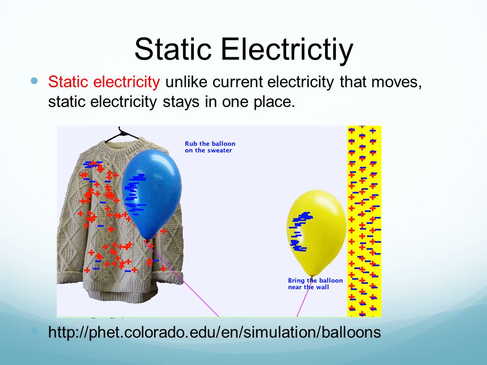
Static Electrictiy Static electricity unlike current electricity that moves, static electricity stays in one place. http://phet.colorado.edu/en/simulation/balloons
6
Van de Graaff

7
Surplus of electrons is called a negative charge (-). A shortage of electrons is called a positive charge (+). A battery provides a surplus of electrons by chemical reaction. By connecting a conductor from the positive terminal to negative terminal electrons will flow. Dynamic, Current Electricity
. A battery provides a surplus of electrons by chemical reaction. By connecting a conductor from the positive terminal to negative terminal electrons will flow. Dynamic, Current Electricity.")
8
In your CricketSAT Mission Notebook Create a Table to organize the variables and specific characteristics of each. Always put your name and date at the top of your table. QuantityResistanceCurrentVoltage Definition Symbol/ variable equation Unit of measure

9
Water Wheel /Electricity Analogy http://www.cabrillo.edu/~jmccullough/Applets/Flash/Electri city%20and%20Magnetism/WaterAnalogy.swf

10
How you should be thinking about electric circuits: Voltage: a force that pushes the current through the circuit (in this picture it would be equivalent to gravity)
")
11
Voltage A battery positive terminal (+) and a negative terminal (-). The difference in charge between each terminal is the potential energy the battery can provide. This is labeled in units of volts. Water Analogy

12
Current: the actual “substance” that is flowing through the wires of the circuit (electrons!) How you should be thinking about electric circuits:
 How you should be thinking about electric circuits:")
13
Current Uniform flow of electrons thru a circuit is called current. WILL USE CONVENTIONAL FLOW NOTATION ON ALL SCHEMATICS

14
Resistance: friction that impedes flow of current through the circuit (rocks in the river) How you should be thinking about electric circuits:
 How you should be thinking about electric circuits:")
15
Resistance All materials have a resistance that is dependent on cross- sectional area, material type and temperature. A resistor dissipates power in the form of heat

16
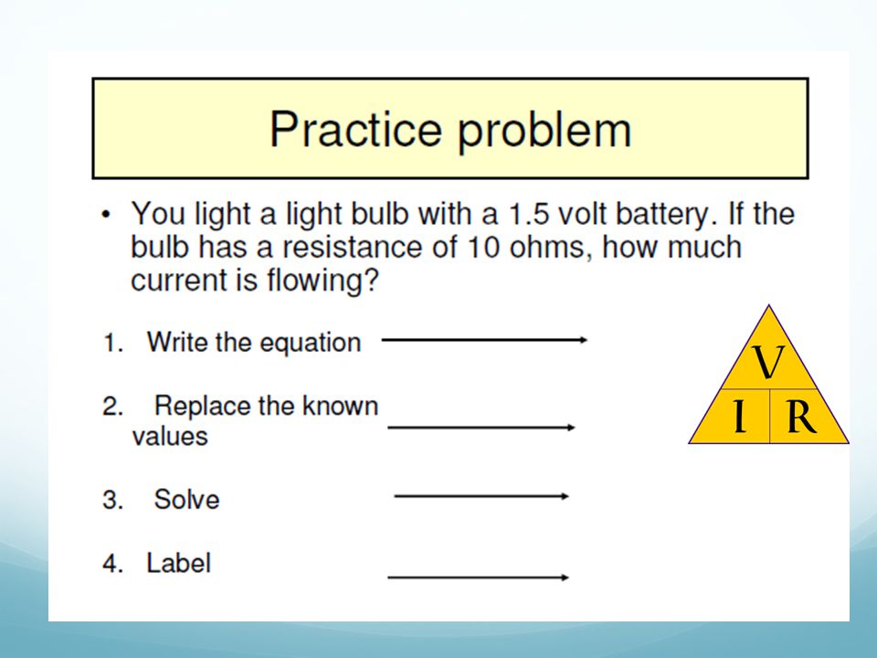
Ohm’s Law V = I R Georg Simon Ohm (1787-1854) I= Current (Amperes) (amps) V= Voltage (Volts) R= Resistance (ohms)
 I= Current (Amperes) (amps) V= Voltage (Volts) R= Resistance (ohms)")
17
Ohms law V = I R defines the relationship between voltage, current and resistance. These basic electrical units apply to direct current, or alternating current. Ohm’s Law is the foundation of electronics and electricity. This formula is used extensively by electricians. Without a thorough understanding of “Ohm’s Law” an electrician can not design or troubleshoot even the simplest of electronic or electrical circuits. Ohm established in the late 1820’s that if a voltage was applied to a resistance then “current would flow and then power would be consumed”.

18
Ohm's law magic triangle Voltage = E or V Current = I Resistance = R

19
Ohm’s Law

20
If you know E and I, and wish to determine R, just eliminate R from the picture and see what's left:

21
If you know E and R, and wish to determine I, eliminate I and see what's left :

22
if you know I and R, and wish to determine E, eliminate E and see what's left:

23
The force or pressure behind electricity variable

24
Symbol for the unit of measure Ω = Ohm

29
milliamp or just mA

30
As a milliampere (milliamp or just mA) is 1/1000th of an ampere, we can convert mA to Amps by just dividing by 1000. Another way is to take the current in mA and move the decimal to the left three places to accomplish the division by 1000. Here's the scoop: 275 mA / 1000 = 0.275 Amps Note that the decimal in 275 is to the right of the 5, and it's written as 275.0 (with a 0 added to show where the decimal is). Moving the decimal to the left three places gets up to.275 Amps, but we usually hang a 0 in front of the decimal. To convert Amps to milliAmps, just multiply by 1000 or move the decimal to the right three places. Just the opposite of what we did here to convert the other way. Conversions of units
. Moving the decimal to the left three places gets up to.275 Amps, but we usually hang a 0 in front of the decimal. To convert Amps to milliAmps, just multiply by 1000 or move the decimal to the right three places. Just the opposite of what we did here to convert the other way. Conversions of units.")
31
Variable

32
Unit Ω = Ohm

36
Break

37
S.MORRIS 2006 ELECTRICAL CIRCUITS More free powerpoints at www.worldofteaching.com

38
Activity Sheet should include your name, date, and the following discovery information as well as you data table and conclusion. Put in your Mission note book under the Electronics Tab. Discovery Activity: Open and Closed Circuits Purpose: Evaluate and create an open and a closed circuit. Materials: Mini light bulb, connecting wire, battery Prediction: Make a prediction of what an open and a closed circuit would be. Procedure: 1. Read all of the directions. Create a data table to record your results. Include draws and explanations. 2.Manipulate the materials in many different ways to light the light bulb. Be sure to draw and explain each trial on your data table. Conclusion: Review and analyze your data collected from the discovery activity. Write a conclusion, What is an open and closed circuit.

39
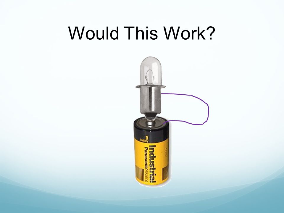
Would This Work?

42
The Central Concept: Closed Circuit

43
circuit diagram cellswitch lamp wires Scientists usually draw electric circuits using symbols;

44
Simple Circuits Series circuit All in a row 1 path for electricity 1 light goes out and the circuit is broken Parallel circuit Many paths for electricity 1 light goes out and the others stay on

45
Series and Parallel Circuit Activity Create an Activity Sheet for the following activity. Purpose: Describe what happens to the current in a series as more resistors are added to the circuit. Prediction: Predict what will happen to the current in a series as more resistors are added. Procedure: Read all of the directions and create a data table to organize the information. Include drawings in your table. Materials: 6 V battery, 3 light bulbs (Christmas lights will work), 6 connector wires
, 6 connector wires.")
46
Part 1 Series Circuit 1. Connect one bulb to the battery creating a closed circuit. Record the relative brightness and draw the circuit. 2. Repeat step 1 and add a second light. Record and draw. 3. Repeat step 2 and add a third light. Record and draw. 4. Remove the middle light. What happened? 5. Conclusion: Write a statement which decribes what happens to the current in a series circuit as you add more resistors (lights)?
 .")
47
The current decreases because the resistance increases. Ohm’s Law says that I=V/R. The voltage in the system is constant, resistance increases. 1 2 3

48
PARALLEL CIRCUIT Place two bulbs in parallel. What do you notice about the brightness of the bulbs? Add a third light bulb in the circuit. What do you notice about the brightness of the bulbs? Remove the middle bulb from the circuit. What happened?

49
The CrickSAT Mission Reflection: Write a reflection paragraph that includes your understanding of the following questions. What connections can you make between Ohm’s Law and The CrickSAT Project? (purpose, importance,???)
.")
Similar presentations


>")


 Electrons (-) Neutrons (0)>")


: What is Ohm’s Law? What do you know about electric circuits? In your own words, what is electric current?>")
 I= Current (Amperes) (amps) V= Voltage (Volts) R= Resistance (ohms)>")
 I= Current (Amperes) (amps) V= Voltage (Volts) R= Resistance (ohms)>")
 240.>")


