Download presentation
Presentation is loading. Please wait.

1
A Semi-Passive Permeable Reactive Barrier (PRB) Remediation Technology Using Membrane-Attached Biofilms Lee Clapp Bala Veerasekaran Vipin Sumani February 5, 2003
 Remediation Technology Using Membrane-Attached Biofilms Lee Clapp Bala Veerasekaran Vipin Sumani February 5, 2003")
2
Chlorinated solvents (e.g., PCE & TCE) are used for industrial vapor degreasing
 are used for industrial vapor degreasing")
3
Problem: Improper disposal of chlorinated solvents

4
DoDDoD 22,089 identified contaminated sites (1995)22,089 identified contaminated sites (1995) 49% contaminated with chlorinated solvents.49% contaminated with chlorinated solvents. Estimated cost of remediation - $28.6 billion.Estimated cost of remediation - $28.6 billion. DOEDOE 10,500 identified contaminated sites (1996)10,500 identified contaminated sites (1996) 25% contaminated with chlorinated solvents.25% contaminated with chlorinated solvents. Estimated cost of remediation - $63 billionEstimated cost of remediation - $63 billion Estimated time for remediation - 75 yearsEstimated time for remediation - 75 years NEED - Development of technologies to reduce remediation costs. (Ref: EPA-542-R-96-005) Magnitude of Problem:
10,500 identified contaminated sites (1996) 25% contaminated with chlorinated solvents.25% contaminated with chlorinated solvents. Estimated cost of remediation - $63 billionEstimated cost of remediation - $63 billion Estimated time for remediation - 75 yearsEstimated time for remediation - 75 years NEED - Development of technologies to reduce remediation costs. (Ref: EPA-542-R ) Magnitude of Problem:.")
5
Water Table Groundwater flow Contaminant Plume Confining Layer Overall Research Goal Hollow-Fiber Membrane Semi-Passive Permeable Reactive Barrier Bacterium Hollow Fiber CH 4 Biofilm Membrane CH 4 DCE CO 2 + Cl - VC CO 2 + Cl - To develop a semi-passive membrane permeable reactive barrier (PRB) remediation technology that fosters biological destruction of chlorinated organic compounds by the controlled delivery of soluble methane & oxygen gas into the subsurface.
 remediation technology that fosters biological destruction of chlorinated organic compounds by the controlled delivery of soluble methane & oxygen gas into the subsurface.")
6
EPA, 2003 DNAPL Contamination

7
EPA, 2003 Recovery of “Free Product”

8
EPA, 2003 Pump & Treat

9
Permeable Reactive Barrier (PRB) Remediation Technology Regenesis, 2003 Wells loaded with HRC or ORC
 Remediation Technology Regenesis, 2003 Wells loaded with HRC or ORC")
10
Geoprobe TM Direct Push Technology

11
H 2 initially detected in these wells & a sampling well 6 ft downstream direction of groundwater flow Passive Membrane PRB System at TCAAP Superfund Site hydrogen added to these wells

12
Two processes for chlorinated solvent biodegradation (1) Reductive dechlorination removes one chlorine at a time (anaerobic). (1) Reductive dechlorination removes one chlorine at a time (anaerobic). (2) Cometabolic oxidation results in >99% mineralization (aerobic). (2) Cometabolic oxidation results in >99% mineralization (aerobic). TCE CO 2 + Cl - O2O2O2O2 CH 4 H 2 HCl H 2 HCl H 2 HCl H 2 HCl PCE TCE cis-DCE VC ETH
 Reductive dechlorination removes one chlorine at a time (anaerobic). (2) Cometabolic oxidation results in >99% mineralization (aerobic). (2) Cometabolic oxidation results in >99% mineralization (aerobic). TCE CO 2 + Cl - O2O2O2O2 CH 4 H 2 HCl H 2 HCl H 2 HCl H 2 HCl PCE TCE cis-DCE VC ETH.")
13
(1) Previous research with reductive dechlorination processes
 Previous research with reductive dechlorination processes")
14
Using hollow-fiber membranes to supply H 2 to contaminated aquifers Geoprobe well ~ 4 cm aquaclude H2H2 flow PCE plume H2H2 HCl PCETCE H 2 gas hollow-fiber membranes TCE DCE VC ETH CH 4 H2H2 HCl DCEVC 4H 2 2H 2 O CO 2 CH 4

15
Problems with enhanced reductive dechlorination for CAH remediation. Accumulation of intermediate transformation products (DCE & VC). Accumulation of intermediate transformation products (DCE & VC). Microbial competition for H 2. Microbial competition for H 2. MCLs below threshold concentrations required for dechlorinator growth. MCLs below threshold concentrations required for dechlorinator growth. Aquifer biofouling. Aquifer biofouling. Adverse impact on groundwater quality. Adverse impact on groundwater quality.
. Accumulation of intermediate transformation products (DCE & VC). Microbial competition for H 2. Microbial competition for H 2. MCLs below threshold concentrations required for dechlorinator growth. MCLs below threshold concentrations required for dechlorinator growth. Aquifer biofouling. Aquifer biofouling. Adverse impact on groundwater quality. Adverse impact on groundwater quality..")
16
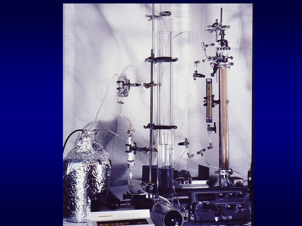
soilcolumnreactors

17
Membrane Module (single fiber) Membrane Module (single fiber)
 Membrane Module (single fiber)")
18
Concentrations of PCE & byproducts in test column (H 2 added) after ~1 year
 after ~1 year")
19
Concentrations of PCE & byproducts in control column (no H 2 ) after ~1 year
 after ~1 year")
20
Concentrations of PCE & byproducts in test column after ~1 year

21
Concentrations of H 2 in control column after ~1 year

22
Model predictions for H 2 concentrations over time

23
Simulated aquifer studies

24
Previous research with cometabolic (aerobic) degradation processes
 degradation processes")
25
TCE plume compressed CH 4 tank air compressor CH 4 explosion hazard, vapor-phase TCE gas-channeling thru porous media vapor treatment blower atmospheric discharge gas extraction well TCE Cl - CO 2 CH 4

26
TCE plume compressed CH 4 tank air compressor What if CH 4 -utilizing bacteria grew as biofilms on surface of membranes? CH 4 O 2 TCE Cl - CO 2 CH 4

29
growing cells utilizing CH 4 non-growing cells cometabolizing TCE Biofilm stratification inactivated cells erosion continuous flux of new cells membrane CH 4 & O 2

30
SEM of biofilm cross-section flux of new cells

31
Biofilm viability staining cells with compromised membranes stained red with propidium iodide viable cells stained green with “Syto 9”

32
Other modeling studies Olaf Cirpka at Stanford has modeled different strategies for minimizing biofouling in aquifers.

33
Two obstacles How can “capture zone” for each well be increased? - Bala How can “capture zone” for each well be increased? - Bala Will presence of copper in groundwater repress expression of operative TCE- degrading enzyme (sMMO)? - Vipin Will presence of copper in groundwater repress expression of operative TCE- degrading enzyme (sMMO)? - Vipin
. - Vipin Will presence of copper in groundwater repress expression of operative TCE- degrading enzyme (sMMO). - Vipin.")
34
Research Topic: Characterizing effect of superimposed transverse flow on well capture zone.

35
Decreasing CH 4 “zone of influence” due to microbial accumulation GW flow

36
Research Objectives Phase 1: Characterize relationship between well-spacing, inter-well pumping rate, and capture zone. Phase 2: Characterize relationship between well-spacing, inter-well pumping rate, and DCE removal efficiency.

37
Modeling Methods: GMS (Groundwater Modeling System) –ModFlow –ModPath –RT3D
 –ModFlow –ModPath –RT3D")
38
Basic Concepts in Groundwater Flow Darcy’s Law: Q x = -K x A (h 2 – h 1 )/L Time taken for a particle to travel t = LnA/Q t-Time,L-Length of the Sample, n-Aquifer porosity, A-Area, Q-Flow Rate
/L Time taken for a particle to travel t = LnA/Q t-Time,L-Length of the Sample, n-Aquifer porosity, A-Area, Q-Flow Rate")
39
Capture Zone: The capture zone defines the area of an aquifer that will contribute water to an extraction well within a specified time period.

40
Well capture zone

41
Assumed Parameter Values Grid: 20 ft 20 ft. Aquifer Hydraulic Conductivity =8.42ft/day Head: Left=10ft, Right=9.57ft Aquifer Porosity=0.35 Well Hydraulic Conductivity=842 ft/day Well Porosity=1.0 Unconfined Aquifer ref: Wilson & MacKay, 1997.

42
Isopotential Lines

43
Particle Paths (Flow Direction)
")
44
Capture zone without pumping Unpumped Well

45
Capture zone with pumping extraction well injection well

46
Conceptualized flow field % capture vs. # of wells & pumping rate

47
Research Topic: Characterizing effect of copper loading on sMMO expression in membrane- attached methanotrophic biofilms.

48
Copper Loading Effect on sMMO Expression in Membrane-Attached Methanotrophic Biofilms Methanotrophs - methane oxidizing bacteria. They are of two types – Type 1 and Type 2. Methane is oxidized by methanotrophs to CO 2 via intermediates like methanol and formaldehyde. Two enzymes sMMO and pMMO play an important role for the oxidation of CH 4. sMMO co-oxidizes a wide range of alkanes & alkenes, including chlorinated hydrocarbons. Cu inhibits sMMO activity.

49
Problems associated with “copper repression of sMMO”

50
CH 4 Oxidation and TCE Degradation Pathways

51
Hypotheses Methanotrophic biofilms can express sMMO at higher copper loading rates than planktonic cultures. Copper will adsorb to the inactive biomass near the biofilm surface. High cell growth rates will dilute copper present in the biofilm interior & thus sMMO expression will not be repressed.

52
membrane wall biofilm liquidfilm Copper will adsorb to surface of counter-diffusional biofilms? TCE CH 4 flux of new cells Cu

53
Research Objectives Characterize sMMO expression as function of: 1. Copper loading. 2. CH 4 /O 2 partial pressures. 3. Time (hard to predict at this moment).
..")
54
Experimental Methods Membrane-attached methanotrophic biofilms will be cultivated. A nitrate mineral salts medium with will be used to supply nutrients (N, P, etc.). High CH 4 and O 2 partial pressures will promote development of thick biofilms.
. High CH 4 and O 2 partial pressures will promote development of thick biofilms..")
55
Membrane-attached methanotrophic biofilm formation

56
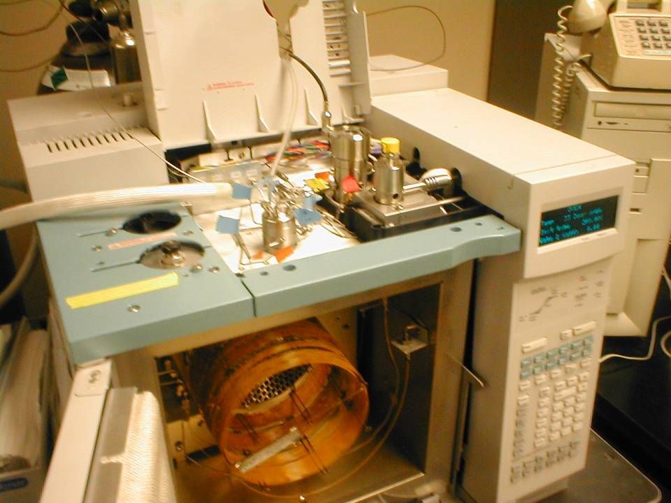
Analytical Methods Headspace GC/ECD (electron capture detector) for TCE. Headspace GC/TCD (thermal conductivity detector) for CH 4. IC for chloride ion. DO meter. pH meter, etc.
 for CH 4. IC for chloride ion. DO meter. pH meter, etc..")
58
Expected Results TCE degradation rate YJ CH4 /J CU pMMO sMMO

Similar presentations


 794-1168.>")


 Great Plains/Rocky Mountain Hazardous.>")

