Download presentation
Presentation is loading. Please wait.

1
PRESENTATION 3 Sri Raguraman CIS 895 Kansas State University

2
Overview of Project Component Design Design Assessment Evaluation Project Evaluation Evaluation User Manual Demo End Product

3
Collect Execution Trace Launch Java application in Eclipse Collect execution trace Only for a section of the application (scenario) XML format Analyze trace Analyze trace xml Generate UML model files Visualize Visualize UML model files as UML diagrams
 XML format Analyze trace Analyze trace xml Generate UML model files Visualize Visualize UML model files as UML diagrams")
4
Launch Target Application Define launch configuration for target application Control which packages/classes/methods to record in trace Collect trace information for a scenario Control when to start or stop trace data collection Upon start, method entry/exit information is recorded Upon stop, the trace file is analyzed and UML2 models generated Visualize UML models

5
Collector Collect execution trace from running application Analyzer Generate UML model files Ui Visualizer Render model files as UML diagrams Each Core functionality is implemented as an Eclipse plug-in. Interface between plug-ins is through extension-points.

7
Defining BRUE Launch configuration Can specify which packages/classes/methods to instrument Instrumenting application Uses Eclipse Probekit to instrument class files Launching application Uses Eclipse launch configuration delegates to launch Java applications.

11
A “Scenario” contains a trace of method entry and method exit events. The events references an id that describes the method details (method name, signature, return type, its class name, package name).
..")
13
Parse trace xml file. Extract packages and classes from trace xml file Build UML2 based models Package model Class model Interaction model

14
Use of Builder pattern

15
UML2 Package Diagram Eclipse GMF used to draw package diagram Contains packages and classes within a package UML2 Class Diagram Eclipse GMF used to draw class diagram One class diagram per package Contains classes and its operations that took part in scenario UML2 Interaction Diagram Eclipse GEF used to draw sequence diagram

16
Use case 1: Launching Java Application and collecting trace data All tests passed Use case 2: Analyzing trace data to generate UML models All tests passed Use case 3: Visualizing UML models All tests passed

19
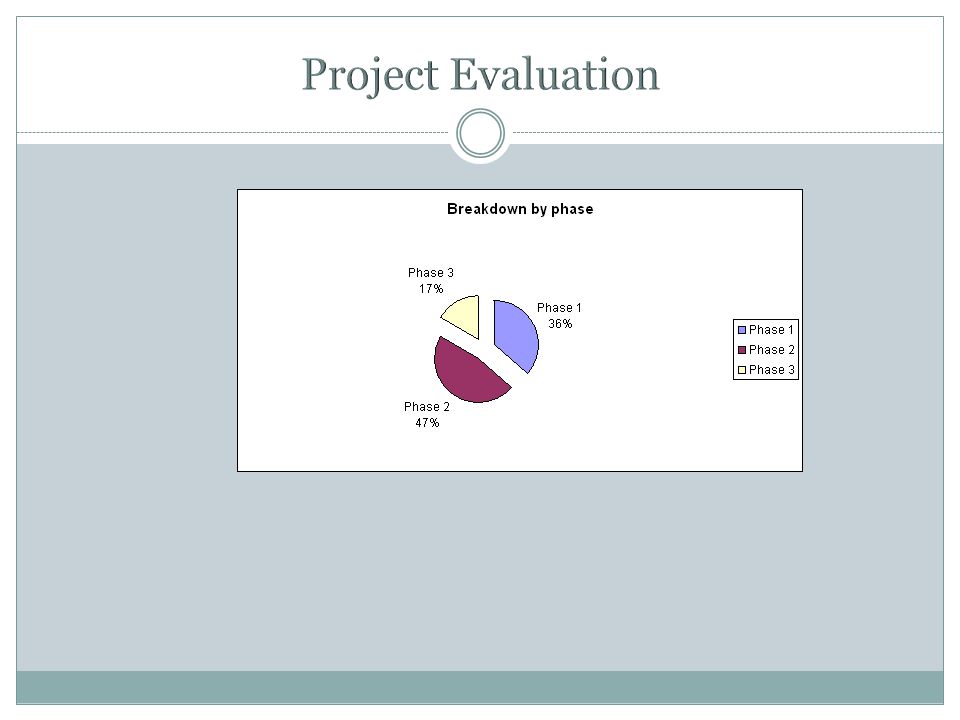
Causes for Phase 2 delay: Needed to understand Eclipse plug-in architecture For static instrumentation, had to understand Eclipse Probekit Eclipse UML2 – Interaction model was hard to understand Causes for Phase 3 delay: New job involved 10 - 12 hour work day Personal commitments which required reshuffling of priorities Eclipse Graphical Editing Framework (GEF) was not easy PhaseExpected finishActual finish Phase 1Feb 23, 2007 Phase 2April 3, 2007July 20, 2007 Phase 3Nov 20, 2007Nov 21, 2008
 was not easy PhaseExpected finishActual finish Phase 1Feb 23, 2007 Phase 2April 3, 2007July 20, 2007 Phase 3Nov 20, 2007Nov 21, 2008")
20
Scope of project was quite large: Instrument source code Launch Java application that uses the instrumented source Collect trace of method calls for a small portion of the system Build UML2 models from the trace Visualize the UML2 models Viable scope of project Collect trace from an instrumented application Build UML2 models

21
The project was an enriching experience. I learnt how to develop Eclipse plug-ins understood Object-oriented design principles how to write and document good quality java code significance of defining scope at the outset the need to balance academic pursuits with professional workload and personal commitments.

22
Demo Questions

Similar presentations


 Explain when to use an adaptive approach to.>")


 – Part One Ku-Yaw Chang Assistant Professor.>")
>")

 2009 J. M. Garrido1 Object Oriented Simulation with Java.>")


