Download presentation
Presentation is loading. Please wait.

1
INTERCEPTION DRAINS, WATERWAYS AND WEIRS Interception drains also - cut-off drains, stormwater drainsalso - cut-off drains, stormwater drains "standard" design is dangerous"standard" design is dangerous estimation of peak runoff, especially where there are unqualified field staff, is most difficult aspect of designestimation of peak runoff, especially where there are unqualified field staff, is most difficult aspect of design Can use Hudson's (if anything, it errs on side of over-design) or similar simple methodCan use Hudson's (if anything, it errs on side of over-design) or similar simple method
 or similar simple methodCan use Hudson s (if anything, it errs on side of over-design) or similar simple method")
3
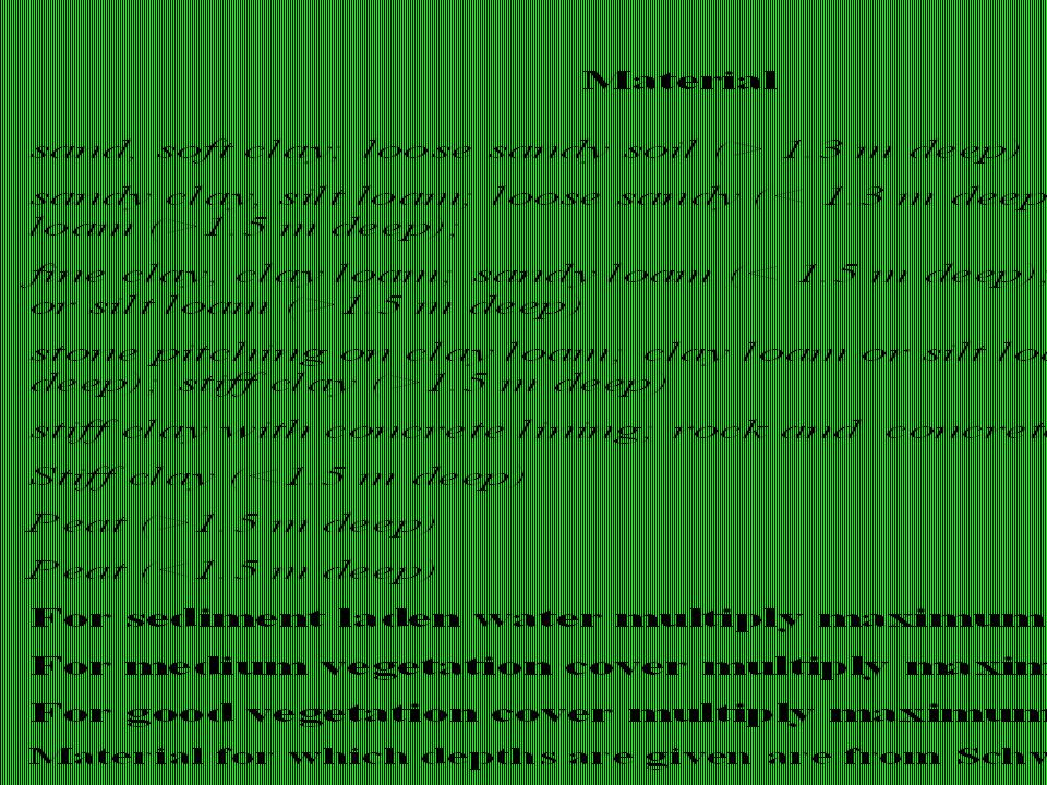
Simplified approach to design of ditches where bottom width equals depth Determine cross section area. Determine side slope and maximum velocity Use following table or data from handout

4
Depth = h = bottom width h h side slope (horizontal / vertical) = z
 = z")
6
Decide on Manning's n value

7
A more detailed list of maximum velocities and Manning’s n can be printed out from the Excel module on Manning's equation Determine minimum depth Cross-sectional area, A is given by where h is the depth and side slope (horizontal : vertical) is z:1 This is shown for a range of side slopes in next 2 graphs. Use them to estimate the depth for a required area.

8
Graph of Area v. depth Figure 1A

9
Figure 1B

10
Determining the minimum hydraulic radius For the given situation, R is given by: where q is the angle of the side slope. R can be estimated from Figure 2. The only unknown now is the required slope of the channel. To do this we first have to find the hydraulic radius from the depth and side slope.

11
Figure 2. Hydraulic radius v. depth

12
Determine the channel slope By rearranging Manning's equation, the slope can be calculated from : If the velocity is at the maximum, the slope is the only unknown. If the velocity is allowed to be less than the maximum, the required cross-sectional area will increase, and so will the required R value. Thus, the maximum slope (and minimum cross-sectional area) is given when the velocity is the maximum allowed.
 is given when the velocity is the maximum allowed..")
13
Maximum grade for channel terraces Thomas (1997) suggests the following maximum slopes for diversion ditches:- light subsoil (sand, silt, sandy loam)0.1 to 0.2 % heavy subsoil (clay and clay loam)0.4 to 0.5%
 suggests the following maximum slopes for diversion ditches:- light subsoil (sand, silt, sandy loam)0.1 to 0.2 % heavy subsoil (clay and clay loam)0.4 to 0.5%")
14
Example Peak flow = 2 m 3 sec -1 Maximum velocity = 1.5 m sec -1, side slope is 1:1 n = 0.03 Thus, minimum cross-sectional area = 2/1.5 = 1.33 m 2 From Figure 1, the minimum cross-sectional area corresponds to a depth of 0.8 m. From Figure 2, this corresponds to a hydraulic radius of about 0.43.

15
From the equation for the slope i.e. 0.63% In practice, slopes are limited to 0.5% for small ditches like this. If we took a velocity of 1.0, the required cross-sectional areas would have been 2 m 2 ; the depth would have been 1 m, the hydraulic radius would have been 0.54 and the slope would be 0.2 %.

16
A grade of 0.5% and a depth of 1 m would therefore work OK because as the slope increases the depth decreases. The relationship between the allowable slopes and allowable depths for this example is given in Figure 3.

17
Figure 3. Relationship between slope and depth for the given example

18
A triangular cross-section - common for channel terraces has a cross-sectional area, A of where h is the centre depth and z:1 (horizontal/vertical) is the side slope of the channel (given for different soil types). Again, the minimum cross-sectional area occurs when the velocity is a maximum. Another special case - triangular cross-section

19
Thus the minimum depth: The hydraulic radius (csa/perimeter) for the triangular section can be shown to be: Note - when h is a minimum, r is a minimum and v is a maximum. So h min can also be written as:

20
From so we can replace this in the equation for h min : So :

21
So:

22
General case for trapeziodal cross-section channels Referring to Figure, the cross-section area, A is given by:

23
We need to solve this for s, but there are an infinity of combinations of depth and width. Trying to solve this analytically soon becomes impossible and the text books recommend a trial and error approach. As before, Manning’s equation is:

24
Fortunately computers allow us to do lots of calculations rapidly and there is an Excel module that can be downloaded that enables various solutions to be selected. Demonstration

25
Waterways If interception drain cannot be discharged directly, construct waterway and take water directly downhill Because some soil borrowed from side of bund, construct short bunds at right angles Should be established with grass (or at least some form of vegetation) before discharge of water from drain. Velocity of water flowing in a channel is related to: slopeslope roughnessroughness shapeshape

26
Manning's equation for shallow flows Used for calculating flow in any channel, but here specifically adapted for calculation of waterway dimension s = slope (s in 1) n = roughness factor R = hydraulic radius of channel (1)
 n = roughness factor R = hydraulic radius of channel (1)")
27
Rearranging (1): and so Must find solution to this where s is slope of land, v is maximum safe velocity or less We can simplifiy this because the width of waterways will normally be large compared with depth.
: and so Must find solution to this where s is slope of land, v is maximum safe velocity or less We can simplifiy this because the width of waterways will normally be large compared with depth.")
28
Ignoring h compared to W on bottom, R is approximately = h (This is why for overland flow, the hydraulic radius is simply the depth of water.) Discharge per unit width of waterway will then be given by: Obtain n & v from tables as before.
 Discharge per unit width of waterway will then be given by: Obtain n & v from tables as before.")
29
Example Find depth and width of waterway to discharge 500 l/sec down slope of 3% over silt loam with moderate vegetation cover. Maximum permissible velocity is 0.75 m/sec; n is 0.033. Slope as decimal is 0.03, so depth of flow is given by: = 0.054 m Thus q = 0.054 x 0.75 cu/m/sec/m =0.0405 cu. m/sec/m = 40.5 l/sec/m

30
Thus waterway should be 500/40.5 = 12.3 m and depth should be 5.4 cm. A safety margin of at least another 10 cm should always be added to the depth of a waterway and so in this case the bund height should be 19 cm. Often the calculated width will be quite wide. If there is a lot of land pressure, the width can be reduced by constructing check dams across the channel to reduce the slope or using lock and spill drains instead. Or split into 2 - one on either edge of farmOr split into 2 - one on either edge of farm

31
By using thick vegetation such as napier grass with a higher n, the width could have been reduced considerably (with a corresponding increase in the allowable depth of water)By using thick vegetation such as napier grass with a higher n, the width could have been reduced considerably (with a corresponding increase in the allowable depth of water) If check dams are used, it would be possible to cultivate the waterway, creating a kind of basin irrigation, e.g. for high value crop, preferably with good ground cover.If check dams are used, it would be possible to cultivate the waterway, creating a kind of basin irrigation, e.g. for high value crop, preferably with good ground cover.

32
A more normal cross-section of waterway…

33
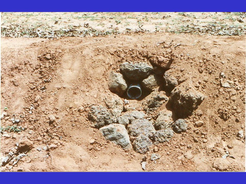
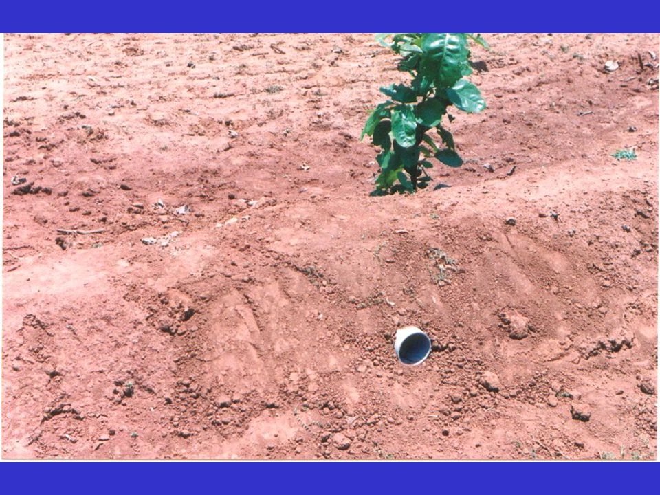
Nalah plugs can function as waterways

34
Broad crested weirs Flow over a broad crested weir such as one you may have in a field bund to discharge surplus flow is given by: Q = 1.7 B h 1.5 where B is the width of the weir (m); h is the depth of flow over the weir (m); Q is the discharge (m 3 /sec)
; h is the depth of flow over the weir (m); Q is the discharge (m 3 /sec)")
38
Lock and spill drains

Similar presentations


>")


