Download presentation
Presentation is loading. Please wait.

1
HokieSat Thermal System Michael Belcher Thermal Lead December 11, 2002

2
Introduction Thermal modeling Software Calculations Results from analysis Conclusions Future plans

3
Heat Transfer Fundamentals Convection Q = h convection A( T) Conduction Q = G( T) Radiation Q = A (T 2 4 -T 1 4 ) Heat transfer in space occurs through conduction and radiation only
 Conduction Q = G( T) Radiation Q = A (T 2 4 -T 1 4 ) Heat transfer in space occurs through conduction and radiation only")
4
Thermal Model Predicts temperatures of spacecraft components Identifies problem areas Useful in analyzing existing design Usually software based TSS, SINDA, TRAYSIS, SSPTA, I-DEAS

5
SSPTA Simplified Space Payload Thermal Analyzer Evaluation/ Educational Software from Swales Aerospace Consists of several smaller programs, which calculate view factors, radiation couplings, absorbed heat loads Used in conjunction with SINDA

6
SINDA Systems Integrated Numerical Differential Analyzer Freeware Calculates temperatures based on a network of thermal nodes Solves network using finite difference method

7
SSPTA Models

10
Radiation Surface Properties

11
Conduction Couplings Calculated in Excel Q = G( T) G = hA Value of h dependant upon: Interface type Conduction coefficient
 G = hA Value of h dependant upon: Interface type Conduction coefficient")
12
Conduction Couplings

13
Thermal Models Created separately for independent verification and ease of use Stand-alone models Battery box CEE External Integrated model Internal, external, battery box, CEE

14
Hot and Cold Case Parameters

15
Model Results: CEE Preliminary results showed need for a thermal filler around bolted interfaces

16
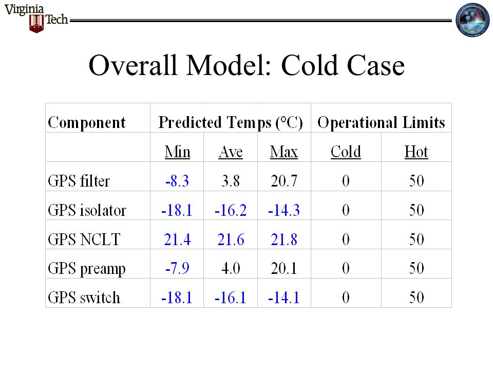
Overall Model: Cold Case

19
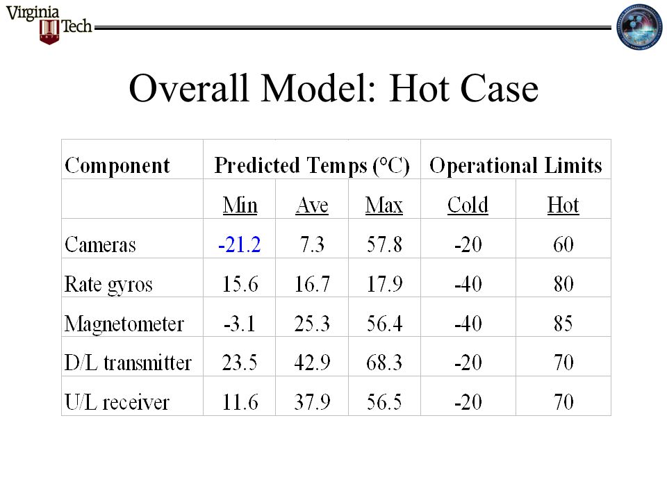
Overall Model: Hot Case

22
Parametric Study: Battery Box Assumed thermal filler (h = 14000 W/m 2 °C) used at bolted interface between battery box frame and nadir panel
 used at bolted interface between battery box frame and nadir panel")
23
Parametric Study: Effect of h Assumed h = 1000 W/m 2 °C at all bolted interfaces Variance of less than ±2 °C in most component temperatures In general, the variance indicated that a lower value of h is conservative

24
Plans Verify G’s with CEE, battery box testing Study effects of MLI Procure interface materials (indium tape) Examine possibility of heater control for cold components Study survival and shuttle bay environments
 Examine possibility of heater control for cold components Study survival and shuttle bay environments")
25
Recap Thermal models Results from models Parametric studies Future plans

26
Conclusions Detailed thermal model of HokieSat has been generated and tested Additional analyses are necessary Verification of model with test data desired Some changes to the thermal design are required

Similar presentations


 G. W. Woodruff School.>")

 can be approximated by a discrete model composed of a.>")


