Download presentation
Presentation is loading. Please wait.

1
Chapter 7: Objectives Part 1
Describe the purpose of the transport layer in managing the transportation of data in end-to-end communication. Describe characteristics of the TCP and UDP protocols, including port numbers and their uses. Part 2 Explain how TCP session establishment and termination processes facilitate reliable communication. Explain how TCP protocol data units are transmitted and acknowledged to guarantee delivery. Explain the UDP client processes to establish communication with a server. Determine whether high-reliability TCP transmissions, or non-guaranteed UDP transmissions, are best suited for common applications.

2
Session Establishment
2

3
Client Sending TCP Requests

4
Request Destination / Source Ports

5
Response Destination / Source Ports

6
Establishing a Session
TCP is reliable because it has connection and session mechanisms. When a host wants to communicate with another host using TCP, a connection must be established before data can be exchanged. This is known as the Three-way Handshake After the communication is completed, the session is closed and the connection is terminated.

7
A TCP Conversation … A B

8
Acknowledgement Number (32) Application Layer Data
Source Port (16) Destination Port (16) Sequence Number (32) Acknowledgement Number (32) Header Length (4) Reserved (6) Control Bits (6) Window (16) Checksum (16) Urgent (16) Options Application Layer Data Control Bits (Flags) (6 bits) Includes bit codes, or flags, that indicate the purpose and function of the TCP segment.
 Destination Port (16) Sequence Number (32) Acknowledgement Number (32) Header Length (4) Reserved (6) Control Bits (6) Window (16) Checksum (16) Urgent (16) Options. Application Layer Data. Control Bits (Flags) (6 bits) Includes bit codes, or flags, that indicate the purpose and function of the TCP segment.")
9
Acknowledgement Number (32) Application Layer Data
TCP Mechanisms The 6 bit TCP Control field contains 1 bit control information used to manage the TCP processes. Fields are referred to as flags and are 1 bit long. It can only contain 1 of 2 values: 0 or a 1. A bit value = 1: indicates control information is contained. Source Port (16) Destination Port (16) Sequence Number (32) Acknowledgement Number (32) Header Length (4) Reserved (6) Control Bits (6) Window (16) Checksum (16) Urgent (16) Options Application Layer Data
 Destination Port (16) Sequence Number (32) Acknowledgement Number (32) Header Length (4) Reserved (6) Control Bits (6) Window (16) Checksum (16) Urgent (16) Options. Application Layer Data.")
10
TCP Control Bits There are 6 bits that are used by the TCP:
URG - (0x020) Urgent pointer field significant ACK - (0x010) Acknowledgement field significant PSH - (0x004) Push function RST - (0x003) Reset the connection SYN - (0x002) Synchronize sequence numbers FIN - (0x001) No more data from sender Used in three-way handshake. NOTE: Other flags are either reserved for future use or for special functions and are beyond the scope of this course.
 Urgent pointer field significant. ACK - (0x010) Acknowledgement field significant. PSH - (0x004) Push function. RST - (0x003) Reset the connection. SYN - (0x002) Synchronize sequence numbers. FIN - (0x001) No more data from sender. Used in. three-way handshake. NOTE: Other flags are either reserved for future use or for special functions and are beyond the scope of this course.")
11
Connection Establishment Phase
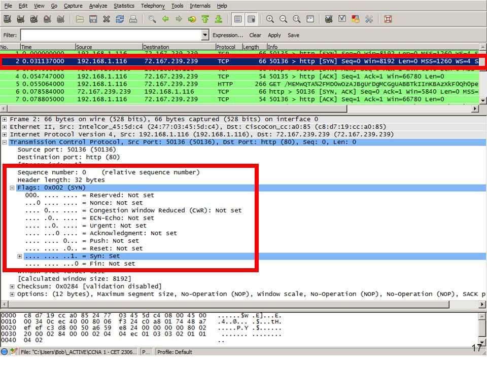
When two hosts communicate using TCP, a connection is established before data can be exchanged. To establish the connection, hosts use a three-way handshake flagging with the SYN and ACK control bits in the TCP header. The three-way handshake: Establishes that the destination device is present on the network. Verifies that the destination device has an active service and is accepting requests on specified destination port number. Informs the destination device that the source client intends to establish a communication session on that port number.

12
Connection Establishment Phase
The 1st host sends an Initial Sequence Number (ISN): The SYN flag set to binary 1. All other control bits (ACK, FIN, RST, URG, and PSH) are set to binary 0.
: The SYN flag set to binary 1. All other control bits (ACK, FIN, RST, URG, and PSH) are set to binary 0.")
13
Connection Establishment Phase
The 2nd host receives the 1st host’s ISN and replies with: An Acknowledgment (ACK) consisting of the 1st host’s ISN + 1. This is called an expectational acknowledgement – the next byte this host expects to receive And it’s own Initial Sequence Number (ISN). The reply is flagged with SYN and ACK set to binary 1.
 consisting of the 1st host’s ISN + 1. This is called an expectational acknowledgement – the next byte this host expects to receive. And it’s own Initial Sequence Number (ISN). The reply is flagged with SYN and ACK set to binary 1.")
14
Connection Establishment Phase
The 1st host receives the ACK and recognizes its ISN+1 and replies with: An ACK consisting of the 2nd host’s ISN + 1. The 1st host’s next sequence number (SN). The ACK flag is set to binary 1
. The ACK flag is set to binary 1.")
15
TCP Three-Way Handshake
PC1 Server PC1 requests a client-to-server communication session. The Server acknowledges the client-to-server communication session and requests a server-to-client communication session. Send SYN SN: 100 CTRL= SYN The initial request contains PC1’s ISN and flags the SYN bit. 100 SYN Received The response consists of the Server’s ISN and PC1’s ISN + 1 with the SYN and ACK bits flagged. 300 = 101. Send SYN, ACK SN: 300 ACK: 101 CTRL= SYN, ACK SYN, ACK Received PC1acknowledges the server-to-client communication session. Send ACK SN: 101 ACK: 301 CTRL= ACK ACK Received The final response consists of PC1’s next SN and the Server’s ISN + 1 with the ACK bit flagged. 101 = 301. HTTP Request (GET)
")
20
Terminating a Current Session
To close a connection, the Finish (FIN) control flag must be set in the segment header. Each host performs a two-way handshake is used using the FIN segment and an ACK control bits. Therefore, to terminate a single conversation supported by TCP, four exchanges are needed to end both sessions.
 control flag must be set in the segment header. Each host performs a two-way handshake is used using the FIN segment and an ACK control bits. Therefore, to terminate a single conversation supported by TCP, four exchanges are needed to end both sessions.")
21
Connection Termination Phase
The 1st host sends a segment with the FIN bit set. The 2nd host replies with the ACK bit set. The 2nd host sends a segment with the FIN bit set. The 1st host replies with the ACK bit set:

22
Termination Mechanisms

23
Reliable Delivery

24
Segments Can Be Lost Congestion can cause segments to be dropped.
For example, when a receiver is congested it may drop segments. Congestion can be caused by: Traffic faster than a network can transfer it. Multiple computers simultaneously sending segments to a single destination.

25
TCP Provides Reliability
In TCP, clients acknowledge the receipt of segment(s) before the next segment is sent. The sender also starts a timer when it sends a segment, and it retransmits a segment if the timer expires before an acknowledgment arrives.
 before the next segment is sent. The sender also starts a timer when it sends a segment, and it retransmits a segment if the timer expires before an acknowledgment arrives.")
27
TCP Provides Reliability
The sequence number (SN) and acknowledgement (ACK) number are used to confirm receipt of data contained in the transmitted segments. The SN number indicates the relative number of bytes that have been transmitted in this session, including the bytes in the current segment. TCP uses the ACK number sent back to the source to indicate the next byte that the receiver expects to receive. This is called expectational acknowledgement.
 and acknowledgement (ACK) number are used to confirm receipt of data contained in the transmitted segments. The SN number indicates the relative number of bytes that have been transmitted in this session, including the bytes in the current segment. TCP uses the ACK number sent back to the source to indicate the next byte that the receiver expects to receive. This is called expectational acknowledgement.")
28
Reliability - Simplified
Send 1 Receive 1 Send ACK 2 Receive ACK 2 Send 2 Receive 2 Send ACK 3 Receive ACK 3 Send 3 Receive 3 Send ACK 4 Receive ACK 4

29
Managing TCP Sessions 10 bytes Next 10 bytes starting with byte 11
Source Dest. SN ACK # 1028 23 1 10 bytes Source Dest. SN ACK # 23 1028 1 11 Source Dest. SN ACK # 1028 23 11 2 Next 10 bytes starting with byte 11

30
Flow Control

31
TCP Windows Waiting for an acknowledgment after each segment would be very inefficient. To maintain efficiency, TCP actually forwards segments in a “window”. A window specifies the number of segments the sender can forward without receiving an acknowledgment.

32
Flow Control and Reliability
Client Window Size=5,000 Server Window Size=10,000 Flow Control and Reliability The window size specifies the number of bytes, starting with the acknowledgment number, that the receiving host's TCP layer is currently prepared to receive. Included in every TCP segment starting with three-way handshake. TCP is a full duplex service Client and server specify their own window sizes. Flow Control and Reliability The receiving host's TCP layer reports a window size to the sending host's TCP layer. This window size specifies the number of bytes, starting with the acknowledgment number, that the receiving host's TCP layer is currently prepared to receive. Window size is included in every TCP segment sent from client or server starting with three-way handshake. TCP is a full duplex service, client and server specify their own window sizes.

33
Windowing and Flow Control
TCP implements flow control by increasing / decreasing window sizes as required. Referred to a “sliding windows” (coming). Window sizes are variable during the lifetime of a connection. Instead of allowing data to be dropped or lost, a “not ready” indicator can be sent to the sender. Referred to as Flow control. Flow control uses windows to prevent a receiver from being overwhelmed by incoming data.
. Window sizes are variable during the lifetime of a connection. Instead of allowing data to be dropped or lost, a not ready indicator can be sent to the sender. Referred to as Flow control. Flow control uses windows to prevent a receiver from being overwhelmed by incoming data.")
34
My Receive Window: 10,000 My Receive Window: 5,000
Client Window Size=5,000 Server Window Size=10,000 Client’s Send Window: 5,000 Server’s Send Window: 10,000 “I can send 10,000 bytes without hearing an ACK, and I can only receive 5,000 bytes at a time.” “I can send 5,000 bytes without hearing an ACK, and I can only receive 10,000 bytes at a time.” Receive Window Sending host can send only that amount of data before getting an acknowledgment and window update from this (the receiving) host. Send Window (not a TCP field) The TCP Receive Window size of the other host. Client Example Receive Window Size=5,000 bytes – Server can only send 5,000 bytes before it receives an acknowledgement. Send Window Size = 10,000 bytes – Server told the client that it can send the server 10,000 bytes before receiving an acknowledgment. Receive Window The TCP Receive Window size: Amount of receive data (in bytes) that can be buffered by this host, at one time on a connection. Sending host can send only that amount of data before getting an acknowledgment and window update from this (the receiving) host. Send Window (not a TCP field) The TCP Receive Window size of the other host. How much data (in bytes) that can be sent by this host before receiving an acknowledgement from the other host. Client Example Receive Window Size=5,000 bytes – Server can only send 5,000 bytes before it receives an acknowledgement. Send Window Size = 10,000 bytes – Server told the client that it can send the server 10,000 bytes before receiving an acknowledgment.
 host. Send Window (not a TCP field) The TCP Receive Window size of the other host. Client Example. Receive Window Size=5,000 bytes – Server can only send 5,000 bytes before it receives an acknowledgement. Send Window Size = 10,000 bytes – Server told the client that it can send the server 10,000 bytes before receiving an acknowledgment. Receive Window. The TCP Receive Window size: Amount of receive data (in bytes) that can be buffered by this host, at one time on a connection. Sending host can send only that amount of data before getting an acknowledgment and window update from this (the receiving) host. Send Window (not a TCP field) The TCP Receive Window size of the other host. How much data (in bytes) that can be sent by this host before receiving an acknowledgement from the other host. Client Example. Receive Window Size=5,000 bytes – Server can only send 5,000 bytes before it receives an acknowledgement. Send Window Size = 10,000 bytes – Server told the client that it can send the server 10,000 bytes before receiving an acknowledgment.")
35
MSS of 1,000 bytes Client has a Window Size of 5,000 bytes Web Server Client Send Window=5,000 Client Window Size=5,000 Server Window Size=10,000 SEQ=1 (to 1,000) … SEQ=1,001 (to 2,000) SEQ=2,001 (to 3,000) SEQ=3,001 (to 4,000) SEQ=4,001 (to 5,000) This is known as a Stop-and-Wait windowing protocol. Server must wait for acknowledgment before continuing to send data. A better method? Sliding Windows Next! Send Window Byte: This is the last byte that can be sent before receiving an ACK ACK=5,001 Client Window Size=5,000 Send Window: Byte 10,000 Server Window Size=10,000 SEQ=5,001 (to 6,000) … SEQ=6,001 (to 7,000) SEQ=7,001 (to 8,000) This is known as a Stop-and-Wait windowing protocol. Server must wait for acknowledgment before continuing to send data. A better method? Sliding Windows Next! Send Window Byte: This is the last byte that can be sent before receiving an ACK SEQ=8,001 (to 9,000) SEQ=9,001 (to 10,000) Client Window Size=5,000 Send Window: Byte 15,000 ACK=10,001 Server Window Size=10,000 SEQ=10,001 (to 11,000) … ….
 … SEQ=1,001 (to 2,000) SEQ=2,001 (to 3,000) SEQ=3,001 (to 4,000) SEQ=4,001 (to 5,000) This is known as a Stop-and-Wait windowing protocol. Server must wait for acknowledgment before continuing to send data. A better method Sliding Windows. Next! Send Window Byte: This is the last byte that can be sent before receiving an ACK. ACK=5,001. Client Window Size=5,000. Send Window: Byte 10,000. Server Window Size=10,000. SEQ=5,001 (to 6,000) … SEQ=6,001 (to 7,000) SEQ=7,001 (to 8,000) This is known as a Stop-and-Wait windowing protocol. Server must wait for acknowledgment before continuing to send data. A better method Sliding Windows. Next! Send Window Byte: This is the last byte that can be sent before receiving an ACK. SEQ=8,001 (to 9,000) SEQ=9,001 (to 10,000) Client Window Size=5,000. Send Window: Byte 15,000. ACK=10,001. Server Window Size=10,000. SEQ=10,001 (to 11,000) … ….")
36
Windowing Sizes - Example
Send 1 Receive 1 Send 2 Receive 2 Send 3 Receive 3 Send ACK 4 Window size: 3 Receive ACK 4 Send 4 Receive 4 Send 5 Receive 5 Send 6 Receive 6 Send ACK 7 Window size: 3 Receive ACK 7 3 Window = x - Acknowledge after x segments Window = 1 - Acknowledge each segment sent Window = 0 - Stop sending

37
Windows and Acknowledgements
SEQ 1 | Bytes In actual fact, the window specifies the number of “bytes” that the receiving TCP process is currently prepared to receive without acknowledgement. For example: Host B is downloading a 10 KB file from Host A. The Window size is set to 3 KB. Host B downloads 1 KB segments (maximum segment size). SEQ | Bytes SEQ | Bytes ACK = 3001 SEQ | Bytes SEQ | Bytes SEQ | Bytes ACK = 6001
. SEQ 1001 | Bytes SEQ 2001 | Bytes ACK = SEQ 3001 | Bytes SEQ 4001 | Bytes SEQ 5001 | Bytes ACK =")
38
Managing TCP Sessions

39
UDP

40
User Datagram Protocol (UDP)
Connectionless-oriented protocol, described in RFC 768. Advantage of providing for low overhead data delivery. Each UDP segment adds a 8 byte header to the Application layer data. It is a stateless protocol, meaning neither the client, nor the server, is obligated to keep track of the state of the communication session. The UDP PDU is called a datagram, but generically the transport layer is referred to as a segment. UDP datagrams are sent as "best effort". Applications that use UDP include: Domain Name System (DNS) Video Streaming Voice over IP (VoIP)
 Video Streaming. Voice over IP (VoIP)")
41
UDP Protocol UDP is simpler and requires less overhead than TCP.
It is not connection-oriented and does not provide the sophisticated retransmission, sequencing, and flow control mechanisms.

42
UDP Services Unlike TCP, UDP does not provide segmentation or reassembly, or: UDP does not establish a connection between the hosts before data can be sent and received. UDP does not establish a connection between the hosts before data can be sent and received. . Occasionally data is received in a different order than it was sent. UDP does not provide any mechanism for reassembling the data in its original sequence. The data is simply delivered to the application in the order that it arrives. There are no flow control mechanisms within UDP If resources on the destination host become overtaxed, the destination host mostly likely drops data sent until resources become available. Unlike TCP, with UDP there is no mechanism for automatic retransmission of dropped data.

43
No Ordered Data Reconstruction
Segments arriving out-of-order are not reorganized because there are no sequence numbers. Having taken different routes to the destination, the datagrams arrive out of order.

44
UDP Header

45
Application Layer Data
Source Port (16) Destination Port (16) Length (16) Checksum (16) Application Layer Data Sample UDP Datagram
 Destination Port (16) Length (16) Checksum (16) Application Layer Data. Sample UDP Datagram.")
46
Application Layer Data
Source Port (16) Destination Port (16) Length (16) Checksum (16) Application Layer Data Sample UDP Datagram Source Port (16 bits) Number of the calling port. Dynamically assigned to the sending host. Number ranges from 1024 to 65,535. The source port makes it possible to have multiple sessions of FTP running simultaneously.
 Destination Port (16) Length (16) Checksum (16) Application Layer Data. Sample UDP Datagram. Source Port (16 bits) Number of the calling port. Dynamically assigned to the sending host. Number ranges from 1024 to 65,535. The source port makes it possible to have multiple sessions of FTP running simultaneously.")
47
Application Layer Data
Source Port (16) Destination Port (16) Length (16) Checksum (16) Application Layer Data Sample UDP Datagram Destination Port (16 bits) Number of the called port. Usually a number between 1 and 1023. End systems use the same port numbers to select the proper application. E.g., when requesting DNS information the destination port is 53.
 Destination Port (16) Length (16) Checksum (16) Application Layer Data. Sample UDP Datagram. Destination Port (16 bits) Number of the called port. Usually a number between 1 and End systems use the same port numbers to select the proper application. E.g., when requesting DNS information the destination port is 53.")
48
Clients Sending UDP Requests

49
Request Destination / Source Ports

50
Response Destination / Source Ports

51
The early years: 1981 – 1992 “The assignment of numbers is also handled by Jon Postel. If you are developing a protocol or application that will require the use of a link, socket, port, protocol, or network number please contact Jon to receive a number assignment.” (RFC 790) 1981:
 1981:")
52
Jon Postel - Postmaster of the Net
Jon Postel made many significant contributions to the development of the Internet, particularly in the area of standards. He is principally known for being the editor of the Request for Comment (RFC) document series, and for serving as the Internet Assigned Numbers Authority (IANA) until his death. (1943 – 1998)
 document series, and for serving as the Internet Assigned Numbers Authority (IANA) until his death. (1943 – 1998)")
53
Different Destination Port
8080 8080 .20 When specifying an IP address, you can also specify a port number. xxx.xxx.xxx.xxx:port# This combination is called a socket. The terms port number and socket used interchangeably. For example, an HTTP web page request being sent to a web server (port 80) running on a host with a Layer 3 IPv4 address of would be destined to socket :80 You can set up a server to operate on different ports and therefore, hide the service from the outside world. Called port forwarding You set up port forwarding to work on port 8080. Therefore your friends could connect to your web server by using: :8080
 running on a host with a Layer 3 IPv4 address of would be destined to socket :80. You can set up a server to operate on different ports and therefore, hide the service from the outside world. Called port forwarding. You set up port forwarding to work on port Therefore your friends could connect to your web server by using: :8080.")
55
Different Destination Port
6001 6001 0.10 You can set up a server to operate on different ports and therefore, hide the service from the outside world. Called port forwarding For example, you want to access a web cam inside your home network, but everyone but your home uses private IP addresses. So you set up port forwarding to work on a specific port. Therefore you could connect to your web cam by using :6001 Port forwarding is covered in more detail in CCNA 4.

Similar presentations


>")


>")


 Part I.>")
 Basics>")

 Dr. Sanjay P. Ahuja, Ph.D. Fidelity National Financial Distinguished Professor of CIS School of Computing, UNF.>")