Download presentation
Presentation is loading. Please wait.

1
IUCAF SUMMER SCHOOL 2002 MITIGATION TECHNIQUES MITIGATION FACTORS - what is it? what is it good for? by Klaus Ruf

2
IUCAF SUMMER SCHOOL 2002 INTERFERENCE Active Services: Interference normally defined in terms of Signal-to-Interference ratio. The service is interrupted (interfered), when the power ratio in dB becomes negative. Radio Astronomy: The wanted signal is almost always masked by noise.
, when the power ratio in dB becomes negative. Radio Astronomy: The wanted signal is almost always masked by noise..")
3
IUCAF SUMMER SCHOOL 2002 Mitigation Technique used in Radio Astronomy: Integration over time and bandwidth Other (active) services need to restrict bandwidth to increase signal-to-noise (interference) ratio.
 services need to restrict bandwidth to increase signal-to-noise (interference) ratio.")
4
Reduce bandwidth to improve signal to noise ratio IUCAF SUMMER SCHOOL 2002

5
Increase bandwidth to increase sensitivity - - = = IUCAF SUMMER SCHOOL 2002

6
Mitigation Technique used in Radio Astronomy: (cont.) observe large bandwidth intergrate for long time use ultra-stable receivers, e.g. switched receivers develop all kinds of sophisticated observing modes develop very high gain antennas go to high altitude (dessert) sites go to very remote sites, radio quiet zones
 sites go to very remote sites, radio quiet zones.")
7
IUCAF SUMMER SCHOOL 2002 Conclusion: Radio Astronomy has developed and applied mitigation techniques long before this word was used! There is nothing wrong with mitigation techniques!

8
IUCAF SUMMER SCHOOL 2002 What are Mitigation Factors? Mitigation factors are the effect of the application of mitigation techniques, expressed in dB, which can be added to our protection criteria.

9
IUCAF SUMMER SCHOOL 2002 Which factors have been proposed? Who is proposing these factors? What will be the effect?

10
IUCAF SUMMER SCHOOL 2002 IRIDIUM LEO-system, operating at 1621.35-1626.5MHz RA-band 1610.6-1613.8MHz Active antennas:traffic density dependent interference power Intensive negotiations in WP7D, in the US, and Europe

11
IUCAF SUMMER SCHOOL 2002 Proposed mitigation factors, in the absence of filtering: side lobe level interference mitigation factor integration time interference mitigation factor polarisation interference mitigation factor and a few others

12
IUCAF SUMMER SCHOOL 2002 What happened to these factors? They are meanwhile adopted, by WP7D, plus a few more, like tolerable data loss to interference minimum elevation angle for observations Which other factors exist, what will be the effect of their implementation?

19
IUCAF SUMMER SCHOOL 2002 Some practical examples good ones bad ones

20
The beam pattern at 10.6 GHz of the Effelsberg 100 m radio telescope, towards 3C84. field size: 30’ x 12’, flux 20.5 Jy (~ -247 dB(W m -2 Hz -1 )), before the TV satellite was switched on. The beam pattern at 10.6 GHz of the Effelsberg 100 m radio telescope, towards 3C84. field size: 30’ x 12’, flux 20.5 Jy (~ -247 dB(W m -2 Hz -1 )), before the TV satellite was switched on. A field of the sky, 30’ x 12’, 10 degrees away from the satellite. The strong source 3C84 is barely visible. IUCAF SUMMER SCHOOL 2002
), before the TV satellite was switched on. The beam pattern at 10.6 GHz of the Effelsberg 100 m radio telescope, towards 3C84. field size: 30’ x 12’, flux 20.5 Jy (~ -247 dB(W m -2 Hz -1 )), before the TV satellite was switched on. A field of the sky, 30’ x 12’, 10 degrees away from the satellite. The strong source 3C84 is barely visible. IUCAF SUMMER SCHOOL")
21
Passband of the filter used to suppress the satellite emissions.

22
IUCAF SUMMER SCHOOL 2002 21cm continuum observation with interference (diagonal stripe in lower left corner) resulting from a strong source.
 resulting from a strong source.")
23
IUCAF SUMMER SCHOOL 2002 The interference was caused by DAB satellite AfriStar.

24
After filtering, AfriStar is invisible in the 21cm band.

26
Field: 2x2 deg. Maximum pfd: 9.3 Jy/beam Field: 2x2 deg. Maximum pfd: 9.3 Jy/beam In the 18 cm band, AfriStar remains visible with moderate pfd level.

27
Field: 2x2 deg Maximum pfd: 43.8 Jy/beam Field: 2x2 deg Maximum pfd: 43.8 Jy/beam

28
The 1.3-1.7 GHz system is a prime focus receiver with cooled HEMT....... To suppress strong radio transmitter signals above 1450 MHz the filter at 1.345 to 1.435 GHz is recommended for sensitive continuum measurements. The 1.3-1.7 GHz system is a prime focus receiver with cooled HEMT....... To suppress strong radio transmitter signals above 1450 MHz the filter at 1.345 to 1.435 GHz is recommended for sensitive continuum measurements. IUCAF SUMMER SCHOOL 2002

29
Further 21 cm continuum measurements.

30
Colour scale: LHC/RHC 1.6 - -0.16 K U/Q 0.12 - -0.16 K elongated feature in RHC: 0.25 Jy/beam integration time: 1 sec/pixel duration of interference: 35 sec Colour scale: LHC/RHC 1.6 - -0.16 K U/Q 0.12 - -0.16 K elongated feature in RHC: 0.25 Jy/beam integration time: 1 sec/pixel duration of interference: 35 sec IUCAF SUMMER SCHOOL 2002

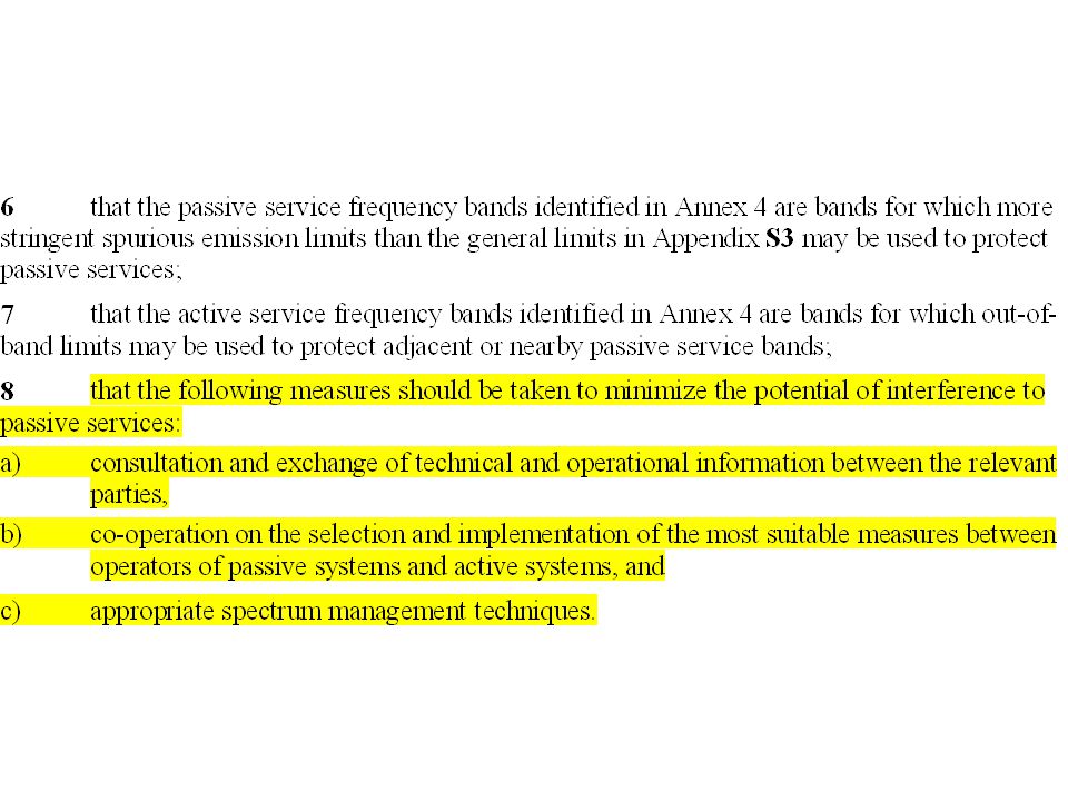
36
Proposed mitigation factors!

37
IUCAF SUMMER SCHOOL 2002 From: The “Rules of Procedure” of the RRB.

38
Spectral emissions Residual carrier due to limited AM index Abs. Bandwidth 3GHz @-10dB fractional BW appr. 12.5% ( per definition WB or UWB ? ) Comb lines of unsmoothed spectrum placed -6dB below power limit for spurious emissions (-30dBm) Power density of smoothed spectrum (appr. -100dBm/Hz) Emissions drop below thermal noise (kT= -174dBm/Hz) at distance of 5m for isotropic receivers No emissions below 20 GHz Traditional VHF/UHF bands are not affected Proposed broadband automotive radar across a passive band at 24 GHz.
 Comb lines of unsmoothed spectrum placed -6dB below power limit for spurious emissions (-30dBm) Power density of smoothed spectrum (appr. -100dBm/Hz) Emissions drop below thermal noise (kT= -174dBm/Hz) at distance of 5m for isotropic receivers No emissions below 20 GHz Traditional VHF/UHF bands are not affected Proposed broadband automotive radar across a passive band at 24 GHz..")
39
IUCAF SUMMER SCHOOL 2002

40
Final Conclusions: Mitigation techniques have been invented by radio astronomers, have always been applied, and still have a great potential for future improvement. Mitigation techniques may be costly and constraining. Need to take the initiative to study and to define, what is achievable and at which price. Mitigation factors are being used to replace the RR!

Similar presentations


 UK Ultra Wide Band (UWB) Compatibility Study Andy Gowans & Bharat Dudhia UK.>")


: Single pixel feeds Theory: Brightness function Beam properties Sensitivity,>")


 Part of this ppt file was originally prepared by Prof. A. R. Thompson.>")
 History and Current Activities Tasso Tzioumis ATNF, CSIRO.>")


 = x dBunits Mike Davis, SETI Institute Spectrum Management Summer School, Green Bank, 6/2002.>")


