Download presentation
Presentation is loading. Please wait.

4
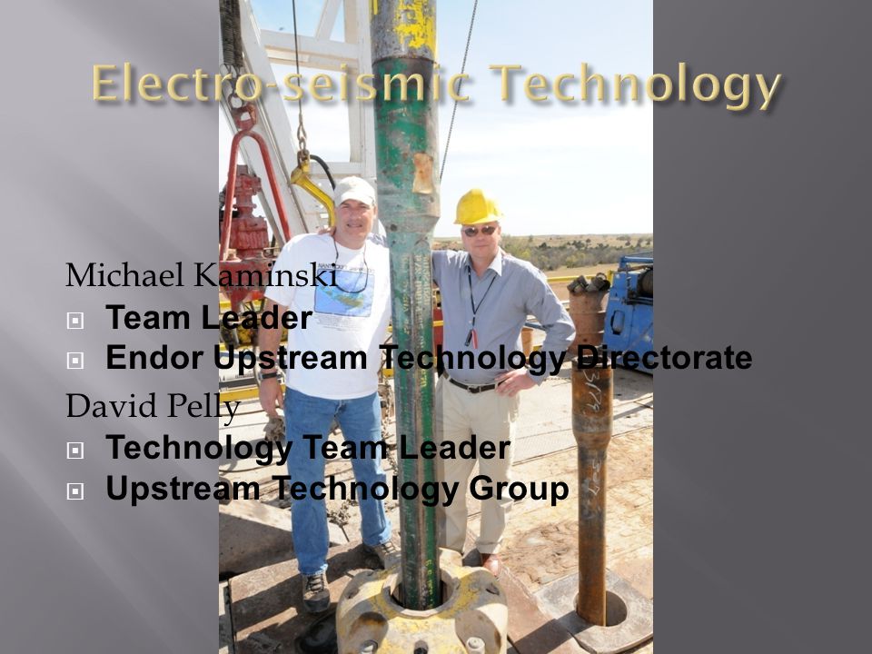
Michael Kaminski Team Leader Endor Upstream Technology Directorate David Pelly Technology Team Leader Upstream Technology Group

5
Detects the presence or absence of hydrocarbon concentration in subsurface traps. Depth of hydrocarbon field. Size and form of hydrocarbon field. Oil Gas Coal CBM Water Geothermal water Radioactive materials Minerals Conventional geophysical methods can only obtain information about the rock matrix, subsurface structures and layers that could bear groundwater, but the presence of water, gas, and oil is only determined once drilling commences.

6
Achieve superior exploration success from a focused, technology-driven balanced exploration program. Seismic acquisition and processing, reservoir imaging, reservoir properties from seismic; basin analysis; seals and structure; seismic interpretation; and visualization. Primary application is in Exploration but also includes application for delineation, exploitation, major capital projects and reservoir management.

7
Improve risk and uncertainty quantification and cycle time reduction through increased investments to address gaps and rebuild organizational capacity in seismic acquisition and processing, seismic analysis; volume interpretation; integrated basin analysis; controlled source acoustical resonance; (CSAR) and development of standard workflows. Endor's commitment to the development of oil, gas, and mineral exploration technologies is reflected in the successful targets developed.

8
(…so is Poindexter!) How do you do it?
 How do you do it")
10
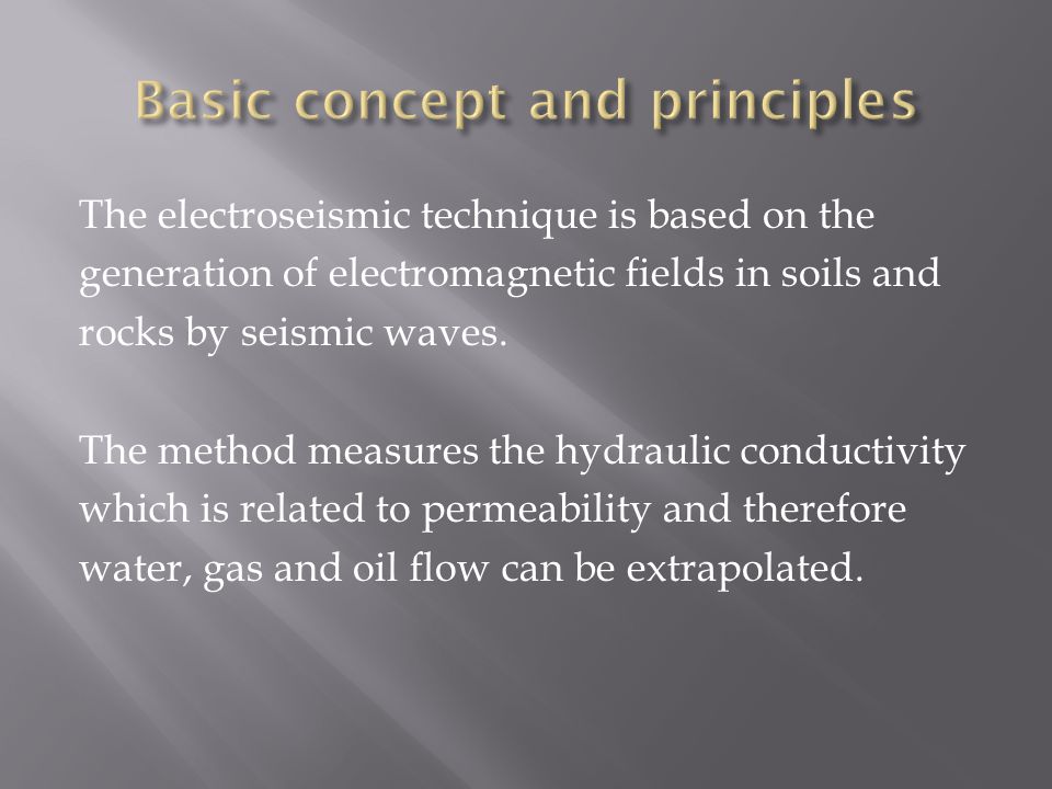
The electroseismic technique is based on the generation of electromagnetic fields in soils and rocks by seismic waves. The method measures the hydraulic conductivity which is related to permeability and therefore water, gas and oil flow can be extrapolated.

11
Based on the phenomenon of electrokinetic signals that are generated through the relative movement of fluids and gases against the sub- surface rock matrix. This movement of the fluids and gases is established through a seismic wave artificially generated at the surface. By proper processing and interpretation of the electrokinetic signal measured at the earth surface, the presence of fluids and gases, the estimated depth and a probable geometry can be determined. What sets this technology apart from conventional geophysical methods is the fact that the presence of presence of fluids and gases is responsible for the generation of electro-seismic signals.

12
The interest of the technique is therefore to measure the electrokinetic effects which are initiated by sound waves passing through a porous rock inducing relative motion of the rock matrix and fluid. When the ionic fluid moves through the rock sample, the cations are attracted to the walls and the applied pressure and resulting fluid movement relative to the rock matrix produces an electric dipole.

13
In the technique of the electroseismics, the electric dipole produced gives a signal. The rise time of the electrical signal is inversely proportional to the rock permeability. The frequency of the signal is determined by the frequency of the pressure pulse and by the permeability of the aquifer. The fluids and gases can move easier and faster in a more permeable rock and generates a higher frequency response than from less permeable rocks. The conductivity of the fluid and gases also determines the amplitude of the signal. Conductive (blackish or saline) water tends to short circuit the signal generating process and reduces the amplitude of signals. Fresh water produces signals that can be several mill volts in amplitude.
 water tends to short circuit the signal generating process and reduces the amplitude of signals. Fresh water produces signals that can be several mill volts in amplitude..")
14
A normal seismic source creates a sharp seismic pulse. This travels through the ground at the velocity of sound. When it enters the matrix containing fluids and gases the fluid, which is less compressible, is forced to move as the rock matrix, more compressible is deformed. Fluid carries ionic charge with it away from the ions of the opposite charge, which are stuck to the pore surfaces. The charge separation distributes the electromagnetic field and the disturbance propagates to the surface at the speed of light.

15
The signals are strongly dependent on at least three main physical properties; porosity of the rock, permeability and fluid chemistry. In theory there is no seismic electric response in partially or unsaturated media so the geological medium must be saturated by an electrolyte. The permeability has a strong influence on streaming potential when the fluid is resistive and hence affects the electro kinetic response as these effects are related and it is why we can detect oil.

16
Furthermore electro kinetic signals are divided into two types. The first type of signal is a non–radiating field, which occurs in homogeneous media and is contained within and travels with the seismic P-waves. The second type of signal is raised when the P-waves passes through a boundary with contrast in elastic and /or electrokinetic’s (fluid-chemistry) properties. The electric signals diffuse rapidly to the sensors with an apparent velocity that is much faster than any seismic wave. Thus the signal will arrive nearly simultaneously across the probe sensor. The second type is the signals that can be used to determine hydrogeological properties.
 properties. The electric signals diffuse rapidly to the sensors with an apparent velocity that is much faster than any seismic wave. Thus the signal will arrive nearly simultaneously across the probe sensor. The second type is the signals that can be used to determine hydrogeological properties..")
17
When a seismic wave encounters an boundry layer interface, it creates a charge separation at the interface forming an electric dipole which can be detected by an probe on the ground surface.

19
Electrokinetic potentials arise because of fluid flow through porous media in response to a pressure difference where = dielectric constant of water (80 0 ), = Zeta potential of mineral surface (~-60 mV), = fluid viscosity, and = fluid conductivity.
, = Zeta potential of mineral surface (~-60 mV), = fluid viscosity, and = fluid conductivity.")
20
The ES Fresnel zones may be defined analogously to the seismic Fresnel zones in Figure above a monochromatic seismic source ( S) is located above a horizontal interface between media of different electrokinetic properties. The spherically spreading seismic wave intersects the interface and causes fluid flow across the interface. Due to the streaming current imbalance at the interface, electric dipole sources oscillating in phase with the seismic wave are created on the interface. EM waves are radiated from the dipole sources and are recorded at the observation point ( M).
..")
21
Where ks = 2 π / λ s is the propagation constant of the seismic wave with a wavelength λ s = vs /f, where vs is the speed of propagation of the seismic wave and f is the source frequency. Similarly kem = 2 π / λ em is the propagation constant of the EM wave with a wavelength λ em = vem /f, where vem is the speed of propagation of the EM wave. Since the speed of propagation of seismic and EM waves in earth material differ by 2 to 3 orders of magnitude, we have kem << ks and the Equation below simplifies to

23
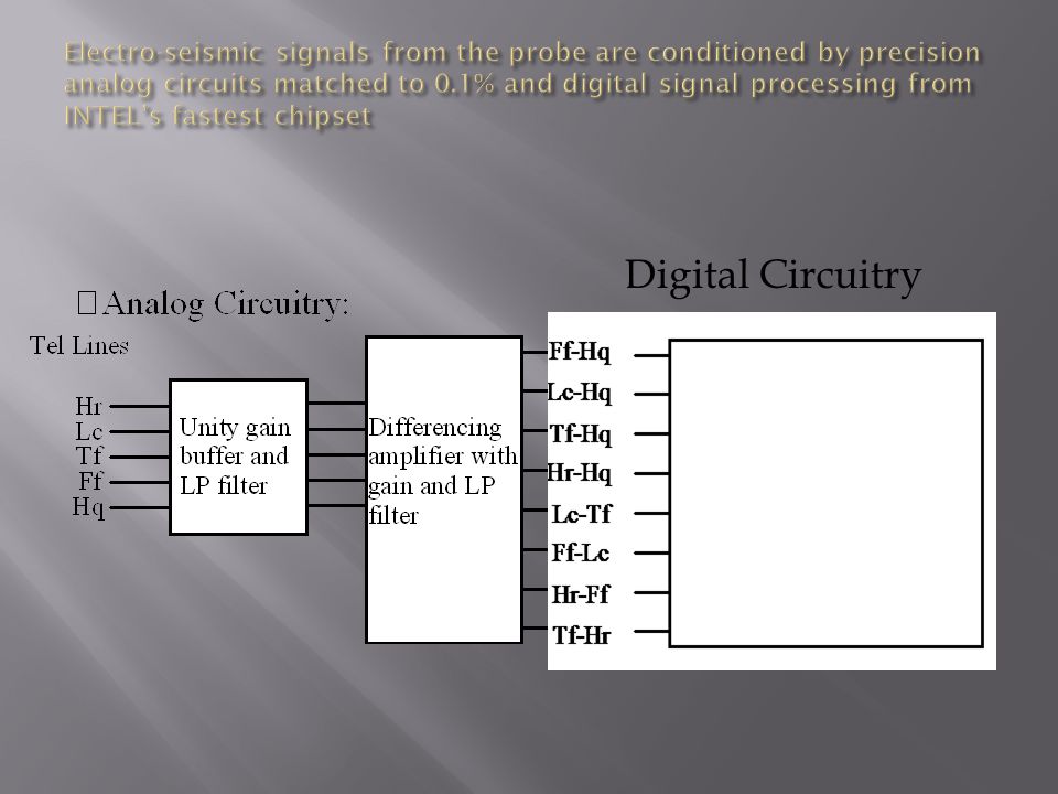
Digital Circuitry

24
The set is mounted in a vehicle for transportation and consist of an electronic module, a computer, probe and a seismic source. The technique relies on the collection, processing and interpretation of electro seismic survey data using a Endor seismic system. The data is collected at various stations and analyzed to selected depths. A probe or probes are arranged in a straight line with one end pointing east so that the probe is across to earths magnetic field. The seismic gun is activated by remote control and data logging begins. The purpose of the source is to send strong, broad–band seismic pulse into the ground. The pulse will stimulate the emissions by the electric signals from porous, permeable rock.

25
The computer records small electrical signals that are induced by the passage of a seismic pulse through saturated porous permeable rock and unconsolidated sediments. Proprietary algorithms built into the Endor seismic system hardware and software interprets the electrical signal. The results are presented as a one-dimensional plot of the Electro kinetic signal in a chromatic display.

26
Electroseismics offers a number of important advantages over other geophysical methods: If there is no electrokinetic signal, it is certain that there is no groundwater, gases or oil and this was confirmed in the sites surveyed during the pilot survey. The equipment for data collection is portable. One person can transport the equipment and undertake surveys. It is very cost effective in that a many of sites can be surveyed in a day and the modeling is very fast.

28
Endor technology identified a high pressure gas zone for a client and issued a recommendation of extreme caution prior to drilling.

Similar presentations


 GPR technology can be used to determine depth to bedrock and or water table, locate buried ordinance at gunnery ranges,>")


 Signal Propagation E. Schrama.>")


>")
