Download presentation
Presentation is loading. Please wait.

1
Zbigniew Leonowicz, PhD
Power-Electronic Systems for the Grid Integration of Renewable Energy Sources Based on: J.M. Carrasco, J.T Bialasiewicz, et al:Power-Electronic Systems for the Grid Integration of Renewable Energy Sources: A Survey, IEEE TRANSACTIONS ON INDUSTRIAL ELECTRONICS, VOL. 53, NO. 4, AUGUST 2006. Zbigniew Leonowicz, PhD

2
Outline New trends in power electronics for the integration of wind and photovoltaic Review of the appropriate storage-system technology Future trends in renewable energy systems based on reliability and maturity

3
Introduction Increasing number of renewable energy sources and distributed generators New strategies for the operation and management of the electricity grid Improve the power-supply reliability and quality Liberalization of the grids leads to new management structures

4
Power-electronics technology
Plays an important role in distributed generation Integration of renewable energy sources into the electrical grid Fast evolution, due to: development of fast semiconductor switches introduction of real-time controllers

5
Outline (detailed) Current technology and future trends in variable-speed wind turbines Power-conditioning systems used in grid-connected photovoltaic (PV) Research and development trends in energy-storage systems
 Research and development trends in energy-storage systems.")
6
Wind turbine technology
Wind-turbine market has been growing at over 30% a year Important role in electricity generation Germany and Spain

7
New technologies - wind turbines
Variable-speed technology – 5% increased efficiency Easy control of active and reactive power flows Rotor acts as a flywheel (storing energy) No flicker problems Higher cost (power electronics cost 7%)
 No flicker problems. Higher cost (power electronics cost 7%)")
8
DFIG

9
Variable-speed turbine with DFIG
Converter feeds the rotor winding Stator winding connected directly to the grid Small converter Low price

10
Simplified semi-variable speed turbine
Rotor resistance of the squirrel cage generator - varied instantly using fast power electronics

11
Variable-Speed Concept Utilizing Full-Power Converter
Decoupled from grid

12
ENERCON multipole synchronous generator reduced losses lower costs
increased reliability

13
Full converter Energy Transfer
Control of the active and reactive powers total-harmonic-distortion control Energy storage CONTROL of Vdc driver controlling the torque generator, using a vector control strategy

14
Rectifier and chopper step-up chopper is used to adapt the
rectifier voltage to the dc-link voltage of the inverter.

15
Semiconductor-Device Technology
Power semiconductor devices with better electrical characteristics and lower prices Insulated Gate Bipolar Transistor (IGBT) is main component for power electronics
 is main component for power electronics.")
16
Integrated gated control thyristor (IGCT) - ABB
 - ABB")
17
Comparison between IGCT and IGBT
IGBTs have higher switching frequency than IGCTs IGCTs are made like disk devices – high electromagnetic emission, cooling problems IGBTs are built like modular devices - lifetime of the device 10 x IGCT IGCTs have a lower ON-state voltage drop- losses 2x lower

18
Grid-Connection Standards for Wind Farms
Voltage Fault Ride-Through Capability of Wind Turbines turbines should stay connected and contribute to the grid in case of a disturbance such as a voltage dip. Wind farms should generate like conventional power plants, supplying active and reactive powers for frequency and voltage recovery, immediately after the fault occurred.

19
Requirements

20
Power-Quality Requirements for Grid-Connected Wind Turbines
- flicker + interharmonics Draft IEC standard for “power-quality requirements for Grid Connected Wind Turbines”

21
IEC Standard IEC-61400-21 Flicker analysis
Switching operations. Voltage and current transients Harmonic analysis (FFT) - rectangular windows of eight cycles of fundamental frequency. THD up to 50th harmonic
 - rectangular windows of eight cycles of fundamental frequency. THD up to 50th harmonic.")
22
Other Standards High-frequency (HF) harmonics and interharmonics IEC and IEC To obtain a correct magnitude of the frequency components, define window width, according to the IEC switching frequency of the inverter is not constant methods for summing harmonics and interharmonics in the IEC Can be not multiple of 50 Hz

23
Transmission Technology for the Future
Offshore installation.

24
HVAC Disadvantages: High distributed capacitance of cables
Limited length

25
HVDC More economic > 100 km and power MW 1) Sending and receiving end frequencies are independent. 2) Transmission distance using dc is not affected by cable charging current. 3) Offshore installation is isolated from mainland disturbances 4) Power flow is fully defined and controllable. 5) Cable power losses are low. 6) Power-transmission capability per cable is higher.
 Sending and receiving end frequencies are independent. 2) Transmission distance using dc is not affected by cable charging current. 3) Offshore installation is isolated from mainland disturbances 4) Power flow is fully defined and controllable. 5) Cable power losses are low. 6) Power-transmission capability per cable is higher.")
26
HVDC LCC-based Line-commutated converters Many disadvantages Harmonics

27
HVDC VSC based HVDC Light – HVDC Plus
Several advantages- flexible power control, no reactive power compensation, …

28
High-Power Medium-Voltage Converter Topologies
Multilevel-converter 1) multilevel configurations with diode clamps 2) multilevel configurations with bidirectional switch interconnection 3) multilevel configurations with flying capacitors 4) multilevel configurations with multiple three-phase inverters 5) multilevel configurations with cascaded single-phase H-bridge inverters.
 multilevel configurations with diode clamps. 2) multilevel configurations with bidirectional switch interconnection. 3) multilevel configurations with flying capacitors. 4) multilevel configurations with multiple three-phase inverters. 5) multilevel configurations with cascaded single-phase H-bridge inverters.")
29
Comparison

30
Multilevel back-to-back converter for direct connection to the grid

31
Low-speed permanent-magnet generators
power-electronic building block (PEBB)
")
32
Direct-Drive Technology for Wind Turbines
Reduced size Lower installation and maintenance cost Flexible control method Quick response to wind fluctuations and load variation Axial flux machines

33
Future Energy-Storage Technologies in Wind Farms
Zinc bromine battery High energy density relative to lead-acid batteries • 100% depth of discharge capability • High cycle life of >2000 cycles at • No shelf life • Scalable capacities from 10kWh to over 500kWh systems • The ability to store energy from any electricity generating source For wind-power application, the flow (zinc bromine) battery system offers the lowest cost per energy stored and delivered. The zinc–bromine battery is very different in concept and design from the more traditional batteries such as the lead–acid battery. The battery is based on the reaction between two commonly available chemicals: zinc and bromine. The zinc–bromine battery offers two to three times higher energy density (75–85 W・ h per kilogram) along with the size and weight savings over the present lead/acid batteries. The power characteristics of the battery can be modified for selected applications. Moreover, zinc–bromine battery suffers no loss of performance after repeated cycling. It has a great potential for renewable energy applications
 battery system offers the lowest cost per energy stored. and delivered. The zinc–bromine battery is very different in. concept and design from the more traditional batteries such. as the lead–acid battery. The battery is based on the reaction. between two commonly available chemicals: zinc and bromine. The zinc–bromine battery offers two to three times higher. energy density (75–85 W・ h per kilogram) along with the size. and weight savings over the present lead/acid batteries. The. power characteristics of the battery can be modified for selected. applications. Moreover, zinc–bromine battery suffers no loss of. performance after repeated cycling. It has a great potential for. renewable energy applications.")
34
Hydrogen as a vehicle fuel
Electrical energy can be produced and delivered to the grid from hydrogen by a fuel cell or a hydrogen combustion generator. The fuel cell produces power through a chemical reaction and energy is released from the hydrogen when it reacts with the oxygen in the air.

35
Variable-speed wind turbine with hydrogen storage system

36
PV Photovoltaic Technology
PV systems as an alternative energy resource Complementary Energy-resource in hybrid systems Necessary: high reliability reasonable cost user-friendly design

37
PV-module connections
The standards EN , IEEE1547, U.S. National Electrical Code (NEC) 690 IEC61727 power quality, detection of islanding operation, grounding structure and the features of the present and future PV modules. Islanding refers to the condition of a distributed generation (DG) generator continuing to power a location even though power from the electric utility is no longer present. Consider for example a building that has solar panels that feed power back to the electrical grid; in case of a power blackout, if the solar panels continue to power the building, the building becomes an "island" with power surrounded by a "sea" of unpowered buildings. Islanding can be dangerous to utility workers, who may not realize that the building is still powered even though there's no power from the grid. For that reason, distributed generators must detect islanding and immediately stop producing power. In intentional islanding, the customer disconnects the building from the grid, and forces the distributed generator to power the building. EN European standard regulating harmonic currents - a brief summary. The IEC standard imposes limits on the harmonic currents drawn from the mains supply. This standard requires that electrical appliances be type tested to ensure that they meet the requirements in the standard. It is applicable to electrical and electronic equipment having an input current up to and including 16A per phase and intended to be connected to public low-voltage distribution systems i.e. supply voltages nominally 230V ac or 415V ac 3 phase. The standard defines four classes of waveform according to the different types of equipment. For example, one of the Classes (Class B) applies to portable tools, whereas the typical switched mode waveform is generally in another Class (Class D). Each Class has different harmonic limits up to the 40th, which must not be exceeded. Some Classes have dynamic limits which are set according to the power drawn by the device. The scope of the EN standard includes products such as lighting equipment, portable tools, all electronic equipment, consumer products and appliances and industrial equipment. This standard does not cover equipment which has a nominal supply voltage less than 220V ac. No limits have been specified for professional equipment above 1kW. Although these requirements cover only products to be sold within EEC countries, a similar IEEE document exists for the USA and Japan is also considering similar legislation. Title Photovoltaic (PV) Systems - Characteristics of the Utility Interface Systèmes photovoltaïques (PV) – Caractéristiques de l'interface de raccordement au réseau International Electrotechnical Commission Publication Date: Dec 1, 2004 Scope: Scope and object This International Standard applies to utility-interconnected photovoltaic (PV) power systems operating in parallel with the utility and utilizing static (solid-state) non-islanding inverters for the conversion of DC to AC. This document describes specific recommendations for systems rated at 10 kVA or less, such as may be utilized on individual residences single or three phase. This standard applies to interconnection with the low-voltage utility distribution system. The object of this standard is to lay down requirements for interconnection of PV systems to the utility distribution system. NOTE 1 An inverter with type certification meeting the standards as detailed in this standard should be deemed acceptable for installation without any futher testing. This standard does not deal with EMC or protection mechanisms against islanding. NOTE 2 Interface requirements may vary when storage systems are incorporated or when control signals for PV system operation are supplied by the utility.
 690. IEC power quality, detection of islanding operation, grounding. structure and the features of the present and future PV modules. Islanding refers to the condition of a distributed generation (DG) generator continuing to power a location even though power from the electric utility is no longer present. Consider for example a building that has solar panels that feed power back to the electrical grid; in case of a power blackout, if the solar panels continue to power the building, the building becomes an island with power surrounded by a sea of unpowered buildings. Islanding can be dangerous to utility workers, who may not realize that the building is still powered even though there s no power from the grid. For that reason, distributed generators must detect islanding and immediately stop producing power. In intentional islanding, the customer disconnects the building from the grid, and forces the distributed generator to power the building. EN European standard regulating harmonic currents - a brief summary. The IEC standard imposes limits on the harmonic currents drawn from the mains supply. This standard requires that electrical appliances be type tested to ensure that they meet the requirements in the standard. It is applicable to electrical and electronic equipment having an input current up to and including 16A per phase and intended to be connected to public low-voltage distribution systems i.e. supply voltages nominally 230V ac or 415V ac 3 phase. The standard defines four classes of waveform according to the different types of equipment. For example, one of the Classes (Class B) applies to portable tools, whereas the typical switched mode waveform is generally in another Class (Class D). Each Class has different harmonic limits up to the 40th, which must not be exceeded. Some Classes have dynamic limits which are set according to the power drawn by the device. The scope of the EN standard includes products such as lighting equipment, portable tools, all electronic equipment, consumer products and appliances and industrial equipment. This standard does not cover equipment which has a nominal supply voltage less than 220V ac. No limits have been specified for professional equipment above 1kW. Although these requirements cover only products to be sold within EEC countries, a similar IEEE document exists for the USA and Japan is also considering similar legislation. Title Photovoltaic (PV) Systems - Characteristics of the Utility Interface. Systèmes photovoltaïques (PV) – Caractéristiques de l interface de raccordement au réseau. International Electrotechnical Commission. Publication Date: Dec 1, Scope: Scope and object. This International Standard applies to utility-interconnected photovoltaic (PV) power systems operating in parallel with the utility and utilizing static (solid-state) non-islanding inverters for the conversion of DC to AC. This document describes specific recommendations for systems rated at 10 kVA or less, such as may be utilized on individual residences single or three phase. This standard applies to interconnection with the low-voltage utility distribution system. The object of this standard is to lay down requirements for interconnection of PV systems to the utility distribution system. NOTE 1 An inverter with type certification meeting the standards as detailed in this standard should be deemed acceptable for installation without any futher testing. This standard does not deal with EMC or protection mechanisms against islanding. NOTE 2 Interface requirements may vary when storage systems are incorporated or when control signals for PV system operation are supplied by the utility.")
38
IEC

39
Islanding PV Generator Converter AC-DC Local Loads Grid

40
Market Considerations PV
Solar-electric-energy growth consistently 20%–25% per annum over the past 20 years 1) an increasing efficiency of solar cells 2) manufacturing-technology improvements 3) economies of scale
 an increasing efficiency of solar cells. 2) manufacturing-technology improvements. 3) economies of scale.")
41
PV growth 2001, 350 MW of solar equipment was sold 2003, 574 MW of PV was installed. In 2004 increased to 927 MW Significant financial incentives in Japan, Germany, Italy and France triggered a huge growth in demand In 2008, Spain installed 45% of all photovoltaics, 2500 MW in 2008 to an drop to 375 MW in 2009

42
Perspectives World solar photovoltaic (PV) installations were gigawatts peak (GWp) in 2007, and 5.95 gigawatts in 2008 The three leading countries (Germany, Japan and the US) represent nearly 89% of the total worldwide PV installed capacity. 2012 are and 12.3GW- 18.8GW expected
 represent nearly 89% of the total worldwide PV installed capacity are and 12.3GW- 18.8GW expected.")
44
Efficiency Market leader in solar panel efficiency (measured by energy conversion ratio) is SunPower, (San Jose USA) % market average of 12-18%. Efficiency of 42% achieved at the University of Delaware in conjunction with DuPont (concentration) in 2007. The highest efficiency achieved without concentration is by Sharp Corporation at 35.8% using a proprietary triple-junction manufacturing technology in 2009.
 in The highest efficiency achieved without concentration is by Sharp Corporation at 35.8% using a proprietary triple-junction manufacturing technology in")
45
Design of PV-Converters
IGBT technology Inverters must be able to detect an islanding situation and take appropriate measures in order to protect persons and equipment PV cells - connected to the grid PV cells - isolated power supplies

47
Converter topologies Central inverters
Module-oriented or module-integrated inverters String inverters The central converters connect in parallel and/or in series on the dc side. One converter is used for the entire PV plant (often divided into several units organized in master–slave mode). The nominal power of this topology is up to several megawatts. The module-oriented converters with several modules usually connect in series on the dc side and in parallel on the ac side. The nominal power ratings of such PV power plants are up to several megawatts. In addition, in the module-integrated converter topology, one converter per PV module and a parallel connection on the ac side are used. In this topology, a central measure for main supervision is necessary.
. The nominal power of this topology is. up to several megawatts. The module-oriented converters with. several modules usually connect in series on the dc side and. in parallel on the ac side. The nominal power ratings of such. PV power plants are up to several megawatts. In addition, in. the module-integrated converter topology, one converter per PV. module and a parallel connection on the ac side are used. In this. topology, a central measure for main supervision is necessary.")
48
Multistring converter
Integration of PV strings of different technologies and orientations

49
Review of PV Converters
S. B. Kjaer, J. K. Pedersen, F.Blaabjerg „A Review of Single-Phase Grid-Connected Inverters for Photovoltaic Modules”, IEEE TRANSACTIONS ON INDUSTRY APPLICATIONS, VOL. 41, NO. 5, SEPTEMBER/OCTOBER 2005 Demands Defined by the Grid - standards (slide 37) EN standard (applied in Europe) allows higher current harmonics the corresponding IEEE and IEC standards.
 EN standard (applied in Europe) allows higher current harmonics. the corresponding IEEE and IEC standards.")
50
limiting the injection is to avoid
saturation of the distribution transformers limits are rather small (0.5% and 1.0% of rated output current), and such small values can be difficult to measure precisely with the exciting circuits inside the inverters. This can be mitigated with improved measuring circuits or by including a line-frequency transformer between the inverter and the grid. Some inverters use a transformer embedded in a high-frequency dc–dc converter for galvanic isolation between the PV modules and the grid. This does not, however, solve the problem with dc injection, but makes the grounding of the PV modules easier.
, and such small values can be difficult to measure precisely. with the exciting circuits inside the inverters. This can be. mitigated with improved measuring circuits or by including a. line-frequency transformer between the inverter and the grid. Some inverters use a transformer embedded in a high-frequency. dc–dc converter for galvanic isolation between the PV modules. and the grid. This does not, however, solve the problem with. dc injection, but makes the grounding of the PV modules. easier.")
51
Islanding Islanding is the continued operation of the inverter when the grid has been removed on purpose, by accident, or by damage Detection schemes - active and passive. The passive methods -monitor grid parameters. The active schemes introduce a disturbance into the grid and monitor the effect. . In other words, the grid has been removed from the inverter, which then only supplies local loads.

52
Grounding & ground faults
The NEC 690 standard - system grounded and monitored for ground faults Other Electricity Boards only demand equipment ground of the PV modules in the case of absent galvanic isolation Equipment ground is the case when frames and other metallic parts are connected to ground.

53
Power injected into grid
Decoupling is necessary p –instantaneous P - average

54
Demands Defined by the Photovoltaic Module
The inverters must guarantee that the PV module(s) is operated at the MPP, which is the operating condition where the most energy is captured. This is accomplished with an MPP tracker (MPPT). maximum power point tracker (or MPPT) is a high efficiency DC to DC converter that presents an optimal electrical load to a solar panel or array and produces a voltage suitable for the load. PV cells have a single operating point where the values of the current (I) and Voltage (V) of the cell result in a maximum power output. These values correspond to a particular resistance, which is equal to V/I as specified by Ohm's Law. A PV cell has an exponential relationship between current and voltage, and the maximum power point (MPP) occurs at the knee of the curve, where the resistance is equal to the negative of the differential resistance (V/I = -dV/dI). Maximum power point trackers utilize some type of control circuit or logic to search for this point and thus to allow the converter circuit to extract the maximum power available from a cell. new technologies like thin-layer silicon, amorphous-silicon, and hoto Electro Chemical (PEC) Voltage in the range from 23 to 38 V at a power generation of approximate 160 W, and their open-circuit voltage is below 45 V. New technolgies - voltage range around V at several hundred amperes per square meter cell
 is operated. at the MPP, which is the operating condition where the most. energy is captured. This is accomplished with an MPP tracker. (MPPT). maximum power point tracker (or MPPT) is a high efficiency DC to DC converter that presents an optimal electrical load to a solar panel or array and produces a voltage suitable for the load. PV cells have a single operating point where the values of the current (I) and Voltage (V) of the cell result in a maximum power output. These values correspond to a particular resistance, which is equal to V/I as specified by Ohm s Law. A PV cell has an exponential relationship between current and voltage, and the maximum power point (MPP) occurs at the knee of the curve, where the resistance is equal to the negative of the differential resistance (V/I = -dV/dI). Maximum power point trackers utilize some type of control circuit or logic to search for this point and thus to allow the converter circuit to extract the maximum power available from a cell. new technologies like thin-layer silicon, amorphous-silicon, and hoto Electro Chemical (PEC) Voltage in the range from 23 to 38 V at a power generation of approximate 160 W, and their open-circuit voltage is below 45 V. New technolgies - voltage range around V at several hundred amperes per square meter cell.")
55
Maximum Power Point Tracker
EX.: ripple voltage should be below 8.5% of the MPP voltage in order to reach a utilization ratio of 98% u is the amplitude of the voltage ripple, PMPP and UMPP are the power and voltage at the MPP, alpha and beta are the coefficients describing a second-order Taylor approximation of the current, and the utilization ratio KPV is given as the average generated power divided by the theoretical MPP power.
![]()
56
Cost Cost effectiveness
using similar circuits as in single-phase power-factor-correction (PFC) circuits variable-speed drives (VSDs)
 circuits. variable-speed drives (VSDs)")
57
High efficiency wide range of input voltage and input power
very wide ranges as functions of solar irradiation and ambient temperature.

58
Meteorological data . (a) Irradiation distribution for a reference year. (b) Solar energy distribution for a reference year. Total time of irradiation equals 4686 h per year. Total potential energy is equal to 1150 kWh=(m2 year) 130 W/m2
 130 W/m2.")
59
Reliability long operational lifetime
most PV module manufacturer offer a warranty of 25 years on 80% of initial efficiency The main limiting components inside the inverters are the electrolytic capacitors used for power decoupling between the PV module and the single-phase grid However, the equation assumes a constant temperature, which can be approximated when the inverter is placed indoors and neglecting the power loss inside the capacitor, but certainly not when the inverter is integrated with the PV module, as for the ac module. In the case of a varying temperature a mean value of (8) must be applied to determine the lifetime
 must be applied to determine the lifetime.")
60
Topologies of PV inverters
Centralized Inverters String Inverters Multi-string Inverters AC modules & AC cell technology

61
Centralized Inverters
PV modules as series connections (a string) series connections then connected in parallel, through string diodes Disadvantages ! high-voltage dc cables between the PV modules and the inverter, power losses due to a centralized MPPT, mismatch losses between the PV modules, losses in the string diodes, and a nonflexible design where the benefits of mass production could not be reached. The grid-connected stage was usually line commutated by means of thyristors, involving many current harmonics and poor power quality. The large amount of harmonics was the occasion of new inverter topologies and system layouts, in order to cope with the emerging standards which also covered power quality.
 series connections then connected in parallel, through string diodes. Disadvantages ! high-voltage dc cables between. the PV modules and the inverter, power losses due to a centralized. MPPT, mismatch losses between the PV modules, losses. in the string diodes, and a nonflexible design where the benefits. of mass production could not be reached. The grid-connected. stage was usually line commutated by means of thyristors, involving many current harmonics and poor power quality. The large amount of harmonics was the occasion of new inverter. topologies and system layouts, in order to cope with the. emerging standards which also covered power quality.")
62
String Inverters Reduced version of the centralized inverter
single string of PV modules is connected to the inverter no losses on string diodes separate MPPTs increases the overall efficiency The input voltage may be high enough to avoid voltage amplification. This requires roughly 16 PV modules in series for European systems. The total open-circuit voltage for 16 PV modules may reach as much as 720 V, which calls for a 1000-V MOSFET/IGBT in order to allow for a 75% voltage de-rating of the semiconductors. The normal operation voltage is, however, as low as 450 510 V. The possibility of using fewer PV modules in series also exists, if a dc–dc converter or line-frequency transformer is used for voltage amplification.

63
AC module inverter and PV module as one electrical device
No mismatch losses between PV modules Optimal adjustment of MPPT high voltage-amplification necessary The ac module depicted in Fig. 3(d) is the integration of the inverter and PV module into one electrical device [7]. It removes the mismatch losses between PV modules since there is only one PV module, as well as supports optimal adjustment between the PV module and the inverter and, hence, the individual MPPT. It includes the possibility of an easy enlarging of the system, due to the modular structure. The opportunity to become a “plugand- play” device, which can be used by persons without any knowledge of electrical installations, is also an inherent feature. On the other hand, the necessary high voltage-amplification may reduce the overall efficiency and increase the price per watt, because of more complex circuit topologies. On the other hand, the ac module is intended to be mass produced, which leads to low manufacturing cost and low retail prices. The present solutions use self-commutated dc–ac inverters, by means of IGBTs or MOSFETs, involving high power quality in compliance with the standards.
 is the integration of the. inverter and PV module into one electrical device [7]. It removes. the mismatch losses between PV modules since there is only one. PV module, as well as supports optimal adjustment between the. PV module and the inverter and, hence, the individual MPPT. It. includes the possibility of an easy enlarging of the system, due. to the modular structure. The opportunity to become a plugand- play device, which can be used by persons without any. knowledge of electrical installations, is also an inherent feature. On the other hand, the necessary high voltage-amplification may. reduce the overall efficiency and increase the price per watt, because of more complex circuit topologies. On the other hand, the ac module is intended to be mass produced, which leads to. low manufacturing cost and low retail prices. The present solutions use self-commutated dc–ac inverters, by means of IGBTs or MOSFETs, involving high power quality. in compliance with the standards.")
64
Future topologies Multi-String Inverters AC Modules AC Cells …

65
Multi-string Inverters
Flexible Every string can be controlled individually. The multi-string inverter depicted in Fig. 3(c) is the further development of the string inverter, where several strings are interfaced with their own dc–dc converter to a common dc–ac inverter [7], [28]. This is beneficial, compared with the centralized system, since every string can be controlled individually. Thus, the operator may start his/her own PV power plant with a few modules. Further enlargements are easily achieved since a new string with dc–dc converter can be plugged into the existing platform. A flexible design with high efficiency is hereby achieved.
 is the further. development of the string inverter, where several strings are interfaced. with their own dc–dc converter to a common dc–ac inverter. [7], [28]. This is beneficial, compared with the centralized. system, since every string can be controlled individually. Thus, the operator may start his/her own PV power plant with a few. modules. Further enlargements are easily achieved since a new. string with dc–dc converter can be plugged into the existing platform. A flexible design with high efficiency is hereby achieved.")
66
AC cell One large PV cell connected to a dc–ac inverter
Very low voltage New converter concepts very low voltage, V and 100Wper square meter, up to an appropriate level for the grid, and at the same time reach a high efficiency. For the same reason, entirely new converter concepts are required.

67
Classification of Inverter Topologies
Single-stage inverter Dual stage inverter Multi-string inverter The inverter of Fig. 4(a) is a single-stage inverter, which must handle all tasks itself, i.e., MPPT, grid current control and, perhaps, voltage amplification. This is the typical configuration for a centralized inverter, with all the drawbacks associated with it. The inverter must be designed to handle a peak power of twice the nominal power, according to (1). Dual-stage inverter. The dc–dc converter is now performing the MPPT (and perhaps voltage amplification). Dependent on the control of the dc–ac inverter, the output from the dc–dc converters is either a pure dc voltage (and the dc–dc converter is only designed to handle the nominal power), or the output current of the dc–dc converter is modulated to follow a rectified sine wave (the dc–dc converter should now handle a peak power of twice the nominal power). The dc–ac inverter is in the former solution controlling the grid current by means of pulsewidth modulation (PWM) or bang-bang operation. In the latter, the dc–ac inverter is switching at line frequency, “unfolding” the rectified current to a full-wave sine, and the dc–dc converter takes care of the current control. A high efficiency can be reached for the latter solution if the nominal power is low. On the other hand, it is advisable to operate the grid-connected inverter in PWM mode if the nominal power is high. multi-string inverter. The only task for each dc–dc converter is MPPT and perhaps voltage amplification. The dc–dc converters are connected to the dc link of a common dc–ac inverter, which takes care of the grid current control. This is beneficial since better control of each PV module/string is achieved and that common dc–ac inverter may be based on standard VSD technology.
 is a single-stage inverter, which must. handle all tasks itself, i.e., MPPT, grid current control and, perhaps, voltage amplification. This is the typical configuration for. a centralized inverter, with all the drawbacks associated with it. The inverter must be designed to handle a peak power of twice. the nominal power, according to (1). Dual-stage inverter. The dc–dc converter is. now performing the MPPT (and perhaps voltage amplification). Dependent on the control of the dc–ac inverter, the output from. the dc–dc converters is either a pure dc voltage (and the dc–dc. converter is only designed to handle the nominal power), or the. output current of the dc–dc converter is modulated to follow a. rectified sine wave (the dc–dc converter should now handle a. peak power of twice the nominal power). The dc–ac inverter. is in the former solution controlling the grid current by means. of pulsewidth modulation (PWM) or bang-bang operation. In. the latter, the dc–ac inverter is switching at line frequency, unfolding the rectified current to a full-wave sine, and the dc–dc. converter takes care of the current control. A high efficiency can. be reached for the latter solution if the nominal power is low. On. the other hand, it is advisable to operate the grid-connected inverter. in PWM mode if the nominal power is high. multi-string inverter. The only task for each dc–dc converter is MPPT and perhaps. voltage amplification. The dc–dc converters are connected to the. dc link of a common dc–ac inverter, which takes care of the grid. current control. This is beneficial since better control of each. PV module/string is achieved and that common dc–ac inverter. may be based on standard VSD technology.")
68
Power Decoupling Capacitors
Power decoupling is normally achieved by means of an electrolytic capacitor. As stated earlier, this component is the main limiting factor of the lifetime. Thus, it should be kept as small as possible and preferably substituted with film capacitors. The capacitor is either placed in parallel with the PV modules or in the dc link between the inverter stages; this is illustrated in Fig. 5. The size of the decoupling capacitor can be expressed as (9) Where Ppv is the nominal power of the PV modules, Uc is the mean voltage across the capacitor, and uc is the amplitude of the ripple. Equation (9) is based on the fact that the current from the PV modules is a pure dc, and that the current drawn from the grid-connected inverter follows a waveform sinus squared, assuming that is constant. CPV = 2,4 miliF CDC =33microF
 Where Ppv is the nominal power of the PV modules, Uc is the. mean voltage across the capacitor, and uc is the amplitude of. the ripple. Equation (9) is based on the fact that the current from. the PV modules is a pure dc, and that the current drawn from. the grid-connected inverter follows a waveform sinus squared, assuming that is constant. CPV = 2,4 miliF. CDC =33microF.")
69
Transformers and Types of Interconnections
Component to avoid (line transformers= high size, weight, price) High-frequency transformers Grounding, The transformer is a paradox within PV inverters. As stated previously, system grounding of the PV modules is not required as long as the maximum output voltage is below 50 V. On the other hand, it is hard to achieve high-efficiency voltage amplification without a transformer, when the input voltage is in the range from 23 to 45 V. Third, the transformer is superfluous when the input voltage becomes sufficiently high. A normal full-bridge inverter cannot be used as grid interface, when both the input and the output of the inverter are be grounded. In addition, the large area of PV modules includes a capacitance of 0.1 nF 10 nF per module to ground [25]. This can also cause severe oscillations between the PV modules and (stray) inductances in the circuit.
 High-frequency transformers. Grounding, The transformer is a paradox within PV inverters. As stated. previously, system grounding of the PV modules is not required. as long as the maximum output voltage is below 50 V. On the. other hand, it is hard to achieve high-efficiency voltage amplification. without a transformer, when the input voltage is in the. range from 23 to 45 V. Third, the transformer is superfluous. when the input voltage becomes sufficiently high. A normal. full-bridge inverter cannot be used as grid interface, when both. the input and the output of the inverter are be grounded. In addition, the large area of PV modules includes a capacitance of. 0.1 nF 10 nF per module to ground [25]. This can also cause. severe oscillations between the PV modules and (stray) inductances. in the circuit.")
70
Types of Grid Interfaces
Inverters operating in current-source mode Fig. 8 shows four, out of many, possible grid-connected inverters. The topologies of Fig. 8(a) and (b) are line-frequency- commutated current-source inverters (CSIs). The current into the stage is already modulated/controlled to follow a rectified sinusoidal waveform and the task for the circuit is simply to re-create the sine wave and inject it into the grid. The circuits apply zero-voltage switching (ZVS) and zero-current switching (ZCS), thus, only conduction losses of the semiconductors remain. Since the current is modulated by another stage, the other stage must be designed for a peak power of twice the nominal power, according to (1) and power decoupling must be achieved with a capacitor in parallel with the PV module(s). The converter feeding the circuit of Fig. 8(a) can be a push–pull with a single secondary transformer winding, and a flyback with two secondary windings for the circuit of Fig. 8(b). Line-commutated CSI switching at twice the line frequency
 and (b) are line-frequency- commutated current-source inverters (CSIs). The. current into the stage is already modulated/controlled to follow. a rectified sinusoidal waveform and the task for the circuit is. simply to re-create the sine wave and inject it into the grid. The. circuits apply zero-voltage switching (ZVS) and zero-current. switching (ZCS), thus, only conduction losses of the semiconductors. remain. Since the current is modulated by another stage, the other. stage must be designed for a peak power of twice the nominal. power, according to (1) and power decoupling must be achieved. with a capacitor in parallel with the PV module(s). The converter. feeding the circuit of Fig. 8(a) can be a push–pull with a. single secondary transformer winding, and a flyback with two. secondary windings for the circuit of Fig. 8(b). Line-commutated CSI switching at twice the line frequency.")
71
Voltage-Source Inverters
standard full-bridge three-level VSI standard full-bridge three-level VSI, which can create a sinusoidal grid current by applying the positive/negative dc-link or zero voltage, to the grid plus grid inductor. The voltage across the grid and inductor is often pulsewidth modulated, but hysteresis (bang-bang) current control can also be applied. A variant of the topology in Fig. 8(c) is the half-bridge two-level VSI, which can only create two distinct voltages across and requires double dc-link voltage and double switching frequency in order to obtain the same performance as the full bridge.
 current control. can also be applied. A variant of the topology in Fig. 8(c) is. the half-bridge two-level VSI, which can only create two distinct. voltages across and requires double dc-link voltage and double. switching frequency in order to obtain the same performance as. the full bridge.")
72
VSI Half-bridge diode-clamped three-level VSI
three-level VSI, is one of many different multilevel VSIs, which can create 3, 5, 7 distinct voltages across the grid and inductor This is beneficial since the switching frequency of each transistor can be reduced and, in the mean time, good power quality is ensured. The command signals for the transistors in the CSI and the reference for the grid-current waveform are mostly based on measured grid voltage or zero-crossing detection. This may result in severe problems with power quality and unnecessary fault situations. According to [8], the main reasons for these problems are the background (voltage) harmonics and poor design. The harmonics may initiate series resonance with the capacitors placed around in the grid (e.g., in refrigerators), due to positive feedback of the inverter current or a noisy signal from the zero-crossing detection. A solution for this problem is to use a phase-locked loop (PLL) for establishing a current waveform reference of high quality.
 harmonics and poor design. The harmonics may initiate series resonance with the capacitors. placed around in the grid (e.g., in refrigerators), due to positive. feedback of the inverter current or a noisy signal from the. zero-crossing detection. A solution for this problem is to use a. phase-locked loop (PLL) for establishing a current waveform. reference of high quality.")
73
AC Modules 100-W single-transistor flyback-type HF-link inverter
100 W, out 230 V, in 48 V, 96%, pf=0,955 The circuit is made up around a single-transistor flyback converter, with a center-tapped transformer. The two outputs from the transformer are connected to the grid, one at a time, through two MOSFETs, two diodes, and a common filter circuit [37]. The flyback converter can, in this way, produce both a positive and a negative output current.

74
AC modules 105-W combined flyback and buck–boost inverter
105 W, out 85V, in 35V, THD <5% The next topology in Fig. 10 is a 105-W combined flyback and buck–boost inverter [38]. The need for a large decoupling capacitor is avoided by adding a buck–boost converter to the flyback converter. The leakage inductance included in the transformer results in a voltage spike across the transistor denoted SDC in Fig. 10, during turn-off. A dissipative RCD clamp would normally be used to remove the overvoltage; see the previous topology.However, theRCD clamp circuit interacts heavily with the buck–boost circuit, causing the inverter to malfunction. The solution is the modified Shimizu topology presented in the next section [39]. Finally, the energy-storing capacitor must carry the entire load current, which increases the demands for its current-ripple capabilities.

75
AC modules Modified Shimizu Inverter (160W, 230, 28V, 87%)
Note that the polarity of the PV module is reversed The inverter in Fig. 11 is an enhanced version of the previous topology, rated for 160 W. The main improvement within this inverter is the replacement of the single-transistor flyback converter with a two-transistor flyback converter, to overcome problems with overvoltage.

76
AC modules 160-W buck–boost inverter in 100V out 160V
The topology in Fig. 12 is a 160-W buck–boost inverter [40]. Again, a small amount of energy is stored in the leakage inductance. This energy is now recovered by the body diodes of transistors and . On the other hand, the diode is blocking for the energy recovery, and no further information is given in [40] about the type of applied clamp circuit.

77
AC modules 150-W flyback dc–dc converter with a line-frequency dc–ac unfolding inverter in 44V, out 120V The topology in Fig. 13 is a 150-W flyback dc–dc converter together with a line-frequency dc–ac unfolding inverter [41]. In [42], the same topology is applied for a 100-W inverter, except that the grid filter is removed from the dc link to the grid side. The line-frequency dc–ac inverter is in both cases equipped with thyristors, which can be troublesome to turn on, since they require a current in their control terminal to turn on.

78
AC modules 100-W flyback dc–dc converter with a PWM dc–ac inverter
30V – 210 V The inverter in Fig. 14 is a 100-W flyback dc–dc converter together with aPWMdc–ac inverter [43], [44]. The output stage is now made up of four transistors, which are switched at high frequency. The grid current is modulated by alternately connecting the positive or the negative dc-link voltage (the constant voltage across ) to the inductor Lgrid in DxTswitch s, and zero voltage in ( is the duty cycle and is the switching period).
 to the inductor Lgrid in DxTswitch s, and zero voltage. in ( is the duty cycle and is the switching. period).")
79
AC modules 110-W series-resonant dc–dc converter with an HF inverter toward the grid 30-230V , 87% The inverter in Fig. 15 is based on a 110-W series-resonant dc–dc converter with an HF inverter toward the grid [36], and 250Win [45]. The series-resonant converter is the first resonant converter visited here. The inverter toward the grid is modified in such a way that is cannot operate as a rectifier, seen from the grid side. Adding two additional diodes does this. The advantage of this solution is that no in-rush current flows when the inverter is attached to the grid for the first time.

80
AC modules dual-stage topology Mastervolt Soladin 120
in 24-40V, out 230V, 91%, pf=0,99 The commercially available Mastervolt Soladin 120 inverter [46] is a “plug-and-play” inverter, based on the topology in Fig. 16. The nominal input power is 90 W at 20–40 V, but the opportunity to operate at peak 120 W exists. The Soladin 120 inverter is a dual-stage topology without inherent power decoupling. The capacitor in parallel with the PV module is, therefore, rather larger (2x 1000 mF at 50 V), since it must work as an energy buffer. According to the work in Section II-B, this results in a small-signal amplitude in the range from 1.8 to 3.0 V, which corresponds to a PV utilization factor from to at full generation.
, since it must work as an. energy buffer. According to the work in Section II-B, this results. in a small-signal amplitude in the range from 1.8 to 3.0 V, which. corresponds to a PV utilization factor from to at full. generation.")
81
String Inverters Single-stage Dual-stage
The string and multi-string systems are the combination of one or several PV strings with a g. the inverters should be of the single- or dual-stage type with or without an embedded HF transformer. Next follow some classical solutions for the string and multi-string inverters.rid-connected inverter

82
String Inverter a transformerless half-bridge diode-clamped three-level inverter The inverter in Fig. 17 is a transformer-less half-bridge diode-clamped three-level inverter [25], [47]. Turning S1 and S2 on can create a positive output voltage, turning S2 and S3 on creates zero voltage, and finally, turning S3 and S4 on creates a negative voltage. Each of the two PV strings is connected to the ground/neutral of the grid, thus, the capacitive earth currents are reduced, and the inverter can easily fulfill the NEC 690 standard. The inverter can be further extended to five levels by adding more transistors, diodes, and PV strings. However, this requires that the outer strings (e.g., the strings placed at locations #0 and #4 in Fig. 17, not illustrated) must be carefully sized since they are loaded differently than strings #1 and #2. Another serious drawback is that string #1 is only loaded during positive grid voltage, and vice versa for string #2. This requires the decoupling capacitors to be enlarged with a factor of approximately Pi , compared to Section IV-B. This is not an advantage for the cost or the lifetime.
 must be carefully sized since they. are loaded differently than strings #1 and #2. Another serious drawback is that string #1 is only loaded during positive grid. voltage, and vice versa for string #2. This requires the decoupling. capacitors to be enlarged with a factor of approximately Pi. , compared to Section IV-B. This is not an advantage for the. cost or the lifetime.")
83
String Inverter two-level VSI, interfacing two PV strings
The inverter in Fig. 18 is a two-level VSI, interfacing two PV strings [48], [49]. This inverter can only produce a two-level output voltage, thus, the switching frequency must be double the previous one in order to obtain the same size of the grid inductor. The main difference between this and the former topology is the generation control circuit (GCC), made by transistors S2 and S3 and inductor Lpv , which can load each PV string independently. Actually, one of the PV strings can even be removed and sinusoidal current can still be injected into the grid. The GCC is an advantage since an individual MPPT can be applied to each string. Further enlargement is easily achieved by adding another PV string plus a transistor, a capacitor, and an inductor. The drawback of this topology and the topology in is their buck characteristic, for which reason the minimum input voltage always must be larger than the maximum grid voltage. For example, the maximum grid voltage is equal to 230Vx root(2)=360V, and the minimum voltage across a PV module is 2,3 V-3 V (MPP voltage minus the 100-Hz ripple across the PV strings). Hence, two strings, each of minimum 18 modules, are required for the former topology and two strings of minimum nine modules for the latter topology.
, made by transistors. S2 and S3 and inductor Lpv , which can load each PV string independently. Actually, one of the PV strings can even be removed. and sinusoidal current can still be injected into the grid. The GCC is an advantage since an individual MPPT can be applied. to each string. Further enlargement is easily achieved by. adding another PV string plus a transistor, a capacitor, and an. inductor. The drawback of this topology and the topology in. is their buck characteristic, for which reason the minimum. input voltage always must be larger than the maximum. grid voltage. For example, the maximum grid voltage is equal. to 230Vx root(2)=360V, and the minimum voltage across a PV. module is 2,3 V-3 V (MPP voltage minus the 100-Hz ripple. across the PV strings). Hence, two strings, each of minimum 18. modules, are required for the former topology and two strings. of minimum nine modules for the latter topology.")
84
SMA Sunny Boy 5000TL three PV strings, each of 2200 W at V, with own MPPT The commercially available inverter (SMA Sunny Boy 5000TL [33], [50]) in Fig. 19 is designed for three PV strings, each of 2200 W at V, and each with their own MPPT. The circuits interfacing the PV strings are standard boost converters, which is beneficial since the HF current ripple at the input terminals of the converters is easily filtered by a film capacitor. The grid-connected dc–ac inverter is a two-level VSI. When this is pointed out, it becomes obvious that the PV strings cannot be system grounded, thus, this inverter is not allowed in the U.S. due to the NEC 690 standard.
 in Fig. 19 is designed for three PV strings, each of 2200 W at V, and each with their own. MPPT. The circuits interfacing the PV strings are standard. boost converters, which is beneficial since the HF current ripple. at the input terminals of the converters is easily filtered by a. film capacitor. The grid-connected dc–ac inverter is a two-level. VSI. When this is pointed out, it becomes obvious that the PV. strings cannot be system grounded, thus, this inverter is not. allowed in the U.S. due to the NEC 690 standard.")
85
PowerLynx Powerlink PV 4.5 kW
three PV strings, each V, 1500 W The dc–dc converters are based on current- source full-bridge inverters with embedded HF transformer and rectifier. The PV strings are easily system grounded and no problem with the NEC 690 standard exists, since this inverter includes galvanic isolation between the PV string and the grid. Once again, the current-source input stage is beneficial since it reduces the requirement for the filter capacitor in parallel with the PV strings. Furthermore, the diodes included in the rectifiers are current commutated which involves low reverse recovery of the diodes and low voltage stress. The grid-connected dc–ac inverter is a three-? level VSI.

86
Evaluation and Discussion
component ratings relative cost lifetime efficiency ratings of the semiconductors are based on the average or rms currents and the peak voltages they have to withstand The relative cost is computed on the basis of the calculated ratings, a component survey at different vendors The lifetime is evaluated by the size of the de-coupling capacitors, and the amount of current they have to carry. A high current involves high power loss in the capacitors, which results in hot spots inside the capacitors, and an increased temperature is the main factor of the lifetime. The efficiency for each inverter has been computed at six different operating points, based on “average” components from the component survey. According to the definition of the European efficiency, the individual efficiencies are weighted and summed up according to

87
Results Dual-stage CSI = large electrolytic decoupling capacitor
VSI = small decoupling electrolytic capacitor. Dual-stage CSIs like the circuits in Fig. 8(a) and (b) suffer from a large electrolytic decoupling capacitor, whereas decoupling for the VSI can be achieved with a small electrolytic capacitor. This is beneficial when lifetime is the issue, since, as already already stated, the electrolytic capacitor is the main limiting single component within the inverters.
 and (b) suffer. from a large electrolytic decoupling capacitor, whereas decoupling. for the VSI can be achieved with a small electrolytic capacitor. This is beneficial when lifetime is the issue, since, as already already. stated, the electrolytic capacitor is the main limiting single. component within the inverters.")
88
Results - Efficiency Low efficiency=87% C=68 mF 160V
High efficiency=93% C=2,2 mF 45V Only two circuits are different from the others when examining the European efficiency; these are the inverters in Figs. 11 and 16. The inverter in Fig. 11 has a low efficiency, which is caused by the high voltage ratings for the semiconductors on the PV side, and in the mean time, high current also flows in the circuit. The push–pull inverter in Fig. 16 has a higher efficiency than the other inverters. This is mainly due to a low conduction loss in the PV-side converter, where only two transistors are carrying the current. On the other hand, the voltage stress for the two transistors is double that of the other inverters (except the one in Fig. 11). This is also seen in the ratings of the semiconductors for this inverter, which are higher than the others. If one should select an inverter topology based on this comparison, the push–pull inverter in Fig. 16 would be a preferable choice, since it offers high efficiency and relatively low price, but attention should be paid to the decoupling capacitor, which is the weakest point.
. This is also seen in the ratings of the semiconductors. for this inverter, which are higher than the others. If one. should select an inverter topology based on this comparison, the. push–pull inverter in Fig. 16 would be a preferable choice, since. it offers high efficiency and relatively low price, but attention. should be paid to the decoupling capacitor, which is the weakest. point.")
89
Discussion - String Inverters
The dual-grounded multilevel inverters p.82 – good solution but quite large capacitors 2x640mF 810V -> half-period loading bipolar PWM switching toward the grid p.83 & 84 (no grounding possible, large ground currents) – 2x1200 mF 375 V current-fed fullbridge dc–dc converters with embedded HF transformers, for each PV string – p.85 – 3x 310 mF 400V The dual-grounded multilevel HBDC inverters can be a good solution, but attention should be paid to the decoupling capacitors, which in the case of the inverter in Fig. 17 must be rather large since they are only loaded in half of the grid period. A solution could be to include some kind of balancing circuit, like the balancing GCC in Fig. 18. Two of the reviewed topologies, (see Figs. 18 and 19) use bipolar PWM switching toward the grid. This is beneficial for the GCC inverter in Fig. 18, but not for the topology in Fig. 19 due to the requirement for a high dc-link voltage and two decoupling capacitors in series to create a midpoint. Besides this, the inverter in Fig. 19 cannot be system grounded which is a requirement from the NEC 690 standard, but common-mode electrical noise at the terminals of the PV module can also generate large ground currents, due to the capacitances from the PV modules to ground. The last topology visited here is based on current-fed fullbridge dc–dc converters with embedded HF transformers, for each PV string. This requires more components than the three previous inverters, but their ratings are lower and the benefits of mass production could be easily achieved. Both commercially available inverters show good efficiency and grid performance.
 – 2x1200 mF 375 V. current-fed fullbridge dc–dc converters with embedded HF transformers, for each PV string – p.85 – 3x 310 mF 400V. The dual-grounded multilevel HBDC inverters can be a good. solution, but attention should be paid to the decoupling capacitors, which in the case of the inverter in Fig. 17 must be rather. large since they are only loaded in half of the grid period. A solution. could be to include some kind of balancing circuit, like. the balancing GCC in Fig. 18. Two of the reviewed topologies, (see Figs. 18 and 19) use. bipolar PWM switching toward the grid. This is beneficial for. the GCC inverter in Fig. 18, but not for the topology in Fig. 19. due to the requirement for a high dc-link voltage and two decoupling. capacitors in series to create a midpoint. Besides this, the. inverter in Fig. 19 cannot be system grounded which is a requirement. from the NEC 690 standard, but common-mode electrical. noise at the terminals of the PV module can also generate large. ground currents, due to the capacitances from the PV modules. to ground. The last topology visited here is based on current-fed fullbridge. dc–dc converters with embedded HF transformers, for. each PV string. This requires more components than the three. previous inverters, but their ratings are lower and the benefits of. mass production could be easily achieved. Both commercially. available inverters show good efficiency and grid performance.")
90
Resume – PV Inverters Large centralized single-stage inverters should be avoided Preferable location for the capacitor is in the dc link where the voltage is high and a large fluctuation can be allowed without compromising the utilization factor HFTs should be applied for voltage amplification in the AC module and AC cell concepts Line-frequency CSI are suitable for low power, e.g., for ac module applications. High-frequency VSI is also suitable for both low- and high-power systems, like the ac module, the string, and the multistring inverters This review has covered some of the standards that inverters for PV and grid applications must fulfill, which focus on power quality,injectionofdccurrentsintothegrid,detectionofislanding operation, and system grounding. The demands stated by the PV modules have also been reviewed; in particular, the role of power decoupling between the modules and the grid has been investigated. An important result is that the amplitude of the ripple across a PV module should not exceed 3.0 V in order to have a utilization efficiency of 98% at full generation. Finally, the basic demands defined by the operator have also been addressed, such as low cost, high efficiency, and long lifetime. The next part of the review was a historical summary of the solutions used in the past, where large areas of PV modules were connected to the grid by means of centralized inverters. This included many shortcomings for which reason the string inverters emerged. A natural development was to add more strings, each with an individual dc–dc converter and MPPT, to the common dc–ac inverter, thus, the multi-string inverters were brought to light. This is believed to be one of the solutions for the future. Another trend seen in this field is the development of the ac module, where each PV module is interfaced to the grid with its own dc–ac inverter. The historical review was followed with a classification of the inverters: number of power processing stages, type of power decoupling between the PV module and the grid, transformers and types of interconnections between the stage, and types of grid interfaces. The conclusions from the classifications are as follows. 1) Large centralized single-stage inverters should be avoided, except if the input voltage is sufficiently high to avoid further amplification. The dual-stage inverter is the solution for ac modules and ac cells, since they require voltage amplification. Last, if several strings are to be connected to the grid, the multi-sting concept seems to be the obvious choice. 2) Nothing is gained by moving the decoupling capacitor from the input of the inverter to the dc link, when PV modules are connected in series to reach a high voltage for the inverter. On the other hand, in the case of the ac module and the ac cell, the preferable location for the capacitor is in the dc link where the voltage is high and a large fluctuation can be allowed without compromising the utilization factor. Electrolytic capacitors should be replaced with film capacitors in order to increase the reliability, but this also involves a higher price, especially for high-power inverters, where a large capacitance is required. On the other hand, a high reliability can be a major sales parameter. 3) HFTs should be applied for voltage amplification in the ac module and ac cell concepts. It is also beneficial to include an HFT in larger systems in order to avoid resonance between the PV modules and inductances in the current main paths. The resonance can, however, also be mitigated with inverter topologies that support grounding on both input and the output terminals. The dual grounding scheme is also a requirement in the U.S. for PV open-circuit voltages larger then 50 V, but not in Europe and Japan. 4) Line-frequency CSIs are suitable for low power, e.g., for ac module applications. On the other hand, a high-frequency VSI is also suitable for both low- and high-power systems, like the ac module, the string, and the multistring inverters.
 Large centralized single-stage inverters should be. avoided, except if the input voltage is sufficiently high to. avoid further amplification. The dual-stage inverter is the. solution for ac modules and ac cells, since they require. voltage amplification. Last, if several strings are to be. connected to the grid, the multi-sting concept seems to. be the obvious choice. 2) Nothing is gained by moving the decoupling capacitor. from the input of the inverter to the dc link, when PV. modules are connected in series to reach a high voltage. for the inverter. On the other hand, in the case of the ac. module and the ac cell, the preferable location for the. capacitor is in the dc link where the voltage is high and a. large fluctuation can be allowed without compromising. the utilization factor. Electrolytic capacitors should be. replaced with film capacitors in order to increase the. reliability, but this also involves a higher price, especially. for high-power inverters, where a large capacitance is. required. On the other hand, a high reliability can be. a major sales parameter. 3) HFTs should be applied for voltage amplification in the. ac module and ac cell concepts. It is also beneficial. to include an HFT in larger systems in order to avoid. resonance between the PV modules and inductances in. the current main paths. The resonance can, however, also be mitigated with inverter topologies that support. grounding on both input and the output terminals. The. dual grounding scheme is also a requirement in the U.S. for PV open-circuit voltages larger then 50 V, but not. in Europe and Japan. 4) Line-frequency CSIs are suitable for low power, e.g., for. ac module applications. On the other hand, a high-frequency. VSI is also suitable for both low- and high-power. systems, like the ac module, the string, and the multistring. inverters.")
91
Converter topologies (general)
PV inverters with dc/dc converter (with or without isolation) PV inverters without dc/dc converter (with or without isolation) Isolation is acquired using a transformer that can be placed on either the grid or low frequency (LF) side or on the HF side Convert_interface p. 10 The isolation used in both categories is acquired using a transformer that can be placed on either the grid or lowfrequency (LF) side or on the HF side. The line-frequency transformer is an important component in the system due to its size, weight, and price. The HF transformer is more compact, but special attention must be paid to reduce losses [34], [37]. The use of a transformer leads to the necessary isolation (requirement in U.S.), and modern inverters tend to use an HF transformer. However, PV inverters with a dc/dc converter without isolation are usually implemented in some countries where grid-isolation is not mandatory.
 PV inverters without dc/dc converter (with or without isolation) Isolation is acquired using a transformer that can be placed on either the grid or low frequency (LF) side or on the HF side. Convert_interface p. 10. The isolation used in both categories is acquired using a. transformer that can be placed on either the grid or lowfrequency. (LF) side or on the HF side. The line-frequency. transformer is an important component in the system due to. its size, weight, and price. The HF transformer is more compact, but special attention must be paid to reduce losses [34], [37]. The use of a transformer leads to the necessary isolation. (requirement in U.S.), and modern inverters tend to use an. HF transformer. However, PV inverters with a dc/dc converter. without isolation are usually implemented in some countries. where grid-isolation is not mandatory.")
92
HF dc/dc converter full-bridge single-inductor push–pull
double-inductor push–pull Basic designs focused on solutions for HF dc/dc converter topologies with isolation such as full-bridge or single-inductor push–pull permit to reduce the transformer ratio providing a higher efficiency together with a smoother input current. However, a transformer with tap point is required. In addition, a double-inductor push–pull is implemented in other kind of applications (equivalent with two interleaved boost converters leading to a lower ripple in the input current), but extra inductor is needed [38]. A full-bridge converter is usually used at power levels above 750 W due to its good transformer utilization [34].
, but extra inductor. is needed [38]. A full-bridge converter is usually used. at power levels above 750 W due to its good transformer. utilization [34].")
93
Another classification
number of cascade power processing stages -single-stage -- dual-stage -----multi-stage There is no any standard PV inverter topology single-stage inverter must handle all tasks such as maximum-power-point-tracking (MPPT) control, grid-current control, and voltage amplification. This configuration, which is useful for a centralized inverter, has some drawbacks because it must be designed to achieve a peak power of twice the nominal power. In this case, the dc/dc converter performs the MPPT (and perhaps voltage amplification), and the dc/ac inverter is dedicated to control the grid current by means of pulsewidth modulation (PWM), space vector modulation (SVM), or bang–bang operation multistage inverters can be used, as mentioned above. In this case, the task for each dc/dc converter is MPPT and, normally, the increase of the dc voltage. The dc/dc converters are connected to the dc link of a common dc/ac inverter, which takes care for the grid-current control. This is beneficial since a better control of each PV module/string is achieved, and that common dc/ac inverter may be based on a standard variablespeed- drive (VSD) technology. Several useful proposed topologies have been presented, and some good studies regarding current PV inverters have been done [39], [40]. The current control scheme is mainly used in PV inverter applications [41]. In these converters, the current into the stage is modulated/controlled to follow a rectified sinusoidal waveform, and the task for the circuit is simply to recreate the sine wave and inject it into the grid. The circuits apply zerovoltage switching (ZVS) and zero-current switching (ZCS). Thus, only conduction losses of the semiconductors remain. If the converter has several stages, power decoupling must be achieved with a capacitor in parallel with the PV module(s). The current control scheme is employed more frequently because a high-power factor can be obtained with simple control circuits, and transient current suppression is possible when disturbances such as voltage changes occur in the utility power system. In the current control scheme, operation as an isolated power source is difficult, but there are no problems with grid interconnection operation. PV automatic-control (AC) module inverters used to be dualstage inverters with an embedded HF transformer. Classical solutions can be applied to develop these converters: flyback converters (single or two transistors), flyback with a buck–boost converter, resonant converters, etc. For string or multistring systems, the inverters used to be single or dual-stage inverters with an embedded HF transformer. However, new solutions try to eliminate the transformer using multilevel topologies. A very common ac/dc topology is the half-bridge two-level VSI, which can create two different voltage levels and requires double dc-link voltage and double switching frequency in order to obtain the same performance as the full bridge. In this inverter, the switching frequency must be double the previous one in order to obtain the same size of the grid inductor. A variant of this topology is the standard full-bridge three-level VSI, which can create a sinusoidal grid current by applying the positive/negative dc-link or zero voltage, to the grid plus grid inductor [42]. This inverter can create three different voltages across the grid and inductor, the switching frequency of each transistor is reduced, and good power quality is ensured. The voltage across the grid and inductor is usually pulsewidth modulated but hysteresis (bang-bang) current control can also be applied. Other multilevel topologies can be taken into account and in [43] cascade multilevel inverters are studied. Seven basic three-level cells can be used to achieve fifteen levels in the output signals without using an output transformer. This is beneficial for the power system and results in an improvement in the THD performance of the output signals. However, other problems such as commutation and conduction losses appear [34].
 control, grid-current. control, and voltage amplification. This configuration, which is. useful for a centralized inverter, has some drawbacks because it. must be designed to achieve a peak power of twice the nominal. power. In this. case, the dc/dc converter performs the MPPT (and perhaps voltage. amplification), and the dc/ac inverter is dedicated to control. the grid current by means of pulsewidth modulation (PWM), space vector modulation (SVM), or bang–bang operation. multistage inverters can be used, as mentioned above. In this case, the task for each dc/dc converter is MPPT and, normally, the increase of the dc voltage. The dc/dc converters. are connected to the dc link of a common dc/ac inverter, which. takes care for the grid-current control. This is beneficial since. a better control of each PV module/string is achieved, and that. common dc/ac inverter may be based on a standard variablespeed- drive (VSD) technology. Several. useful proposed topologies have been presented, and some. good studies regarding current PV inverters have been done. [39], [40]. The current control scheme is mainly used in PV. inverter applications [41]. In these converters, the current into. the stage is modulated/controlled to follow a rectified sinusoidal. waveform, and the task for the circuit is simply to recreate the. sine wave and inject it into the grid. The circuits apply zerovoltage. switching (ZVS) and zero-current switching (ZCS). Thus, only conduction losses of the semiconductors remain. If the converter has several stages, power decoupling must be. achieved with a capacitor in parallel with the PV module(s). The current control scheme is employed more frequently because. a high-power factor can be obtained with simple control. circuits, and transient current suppression is possible when. disturbances such as voltage changes occur in the utility power. system. In the current control scheme, operation as an isolated. power source is difficult, but there are no problems with grid. interconnection operation. PV automatic-control (AC) module inverters used to be dualstage. inverters with an embedded HF transformer. Classical. solutions can be applied to develop these converters: flyback. converters (single or two transistors), flyback with a buck–boost. converter, resonant converters, etc. For string or multistring. systems, the inverters used to be single or dual-stage inverters. with an embedded HF transformer. However, new solutions try. to eliminate the transformer using multilevel topologies. A very common ac/dc topology is the half-bridge two-level. VSI, which can create two different voltage levels and requires. double dc-link voltage and double switching frequency in order. to obtain the same performance as the full bridge. In this. inverter, the switching frequency must be double the previous. one in order to obtain the same size of the grid inductor. A. variant of this topology is the standard full-bridge three-level. VSI, which can create a sinusoidal grid current by applying the. positive/negative dc-link or zero voltage, to the grid plus grid. inductor [42]. This inverter can create three different voltages. across the grid and inductor, the switching frequency of each. transistor is reduced, and good power quality is ensured. The. voltage across the grid and inductor is usually pulsewidth. modulated but hysteresis (bang-bang) current control can also. be applied. Other multilevel topologies can be taken into account and. in [43] cascade multilevel inverters are studied. Seven basic. three-level cells can be used to achieve fifteen levels in the. output signals without using an output transformer. This is. beneficial for the power system and results in an improvement. in the THD performance of the output signals. However, other problems such as commutation and conduction losses. appear [34].")
94
Future very efficient PV cells roofing PV systems
PV modules in high building structures

95
Future trends PV systems without transformers - minimize the cost of the total system cost reduction per inverter watt -make PV-generated power more attractive AC modules implement MPPT for PV modules improving the total system efficiency „ plug and play systems” The increasing interest and steadily growing number of investors in solar energy stimulated research that resulted in the development of very efficient PV cells, leading to universal implementations in isolated locations [44]. Due to the improvement of roofing PV systems, residential neighborhoods are becoming a target of solar panels, and some current projects involve installation and setup of PV modules in high building structures [45]. PV systems without transformers would be the most suitable option in order to minimize the cost of the total system. On the other hand, the cost of the grid-connected inverter is becoming more visible in the total system price. A cost reduction per inverter watt is, therefore, important to make PV-generated power more attractive. Therefore, it seems that centralized converters would be a good option for PV systems. However, 1012 IEEE TRANSACTIONS ON INDUSTRIAL ELECTRONICS, VOL. 53, NO. 4, AUGUST 2006 Fig. 13. Typical compensation system for renewable energy applications based on flywheel energy storage. problems associated with the centralized control appear, and it can be difficult to use this type of systems. An increasing interest is being focused on ac modules that implement MPPT for PV modules improving the total system efficiency. The future of this type of topologies is to develop “plug and play systems” that are easy to install for nonexpert users. This means that new ac modules may see the light in the future, and they would be the future trend in this type of technology. The inverters must guarantee that the PV module is operated at the maximum power point (MPP) owing to use MPPT control increasing the PV systems efficiency. The operation around the MPP without too much fluctuation will reduce the ripple at the terminals of the PV module. Therefore,
 owing to use MPPT control increasing the PV systems. efficiency. The operation around the MPP without too. much fluctuation will reduce the ripple at the terminals of the. PV module. Therefore,")
96
Research MPPT control THD improvements
reduction of current or voltage ripple standards are becoming more and more strict Therefore, the control topics such as improvements of MPPT control, THD improvements, and reduction of current or voltage ripples will be the focus of researchers in the years to come [46]. These topics have been deeply studied during the last years, but some improvements still can be done using new topologies such as multilevel converters. In particular, multilevel cascade converters seem to be a good solution to increase the voltage in the converter in order to eliminate the HF transformer. A possible drawback of this topology is control complexity and increased number of solid-state devices (transistors and diodes). It should be noticed that the increase of commutation and conduction losses has to be taken into account while selecting PWM or SVM algorithms. Finally, it is important to remember that standards, regarding the connection of PV systems to the grid, are actually becoming more and more strict. Therefore, the future PV technology will have to fulfil them, minimizing simultaneously the cost of the system as much as possible. In addition, the incorporation of new technologies, packaging techniques, control schemes, and an extensive testing regimen must be developed. Testing is not only the part of each phase of development but also the part of validation of the final product
. It should be noticed. that the increase of commutation and conduction losses. has to be taken into account while selecting PWM or SVM. algorithms. Finally, it is important to remember that standards, regarding. the connection of PV systems to the grid, are actually becoming. more and more strict. Therefore, the future PV technology will. have to fulfil them, minimizing simultaneously the cost of the. system as much as possible. In addition, the incorporation of. new technologies, packaging techniques, control schemes, and. an extensive testing regimen must be developed. Testing is not. only the part of each phase of development but also the part of. validation of the final product.")
97
STORAGE

98
Energy Storage Systems
Improvement of Quality Support the Grid during Interruption Flywheels – spinning mass energy (commercial application with active filters) In order to improve the quality of the generated power, as well as to support critical loads during mains’ power interruption, several energy-storage technologies have been investigated, developed, proved, and implemented in renewable energy systems. However, flywheels are very commonly used due to the simplicity of storing kinetic energy in a spinning mass. For approximately 20 years, it has been a primary technology used to limit power interruptions in motor/generator sets where steel wheels increase the rotating inertia providing short power interruptions protection and smoothing of delivered power. One of the first commercial uses of flywheels in conjunction with active filtering to improve frequency distortion on a high-voltage power-system line is described in the lit.
 In order to improve the quality of the generated power, as well as to support critical loads during mains’ power interruption, several energy-storage technologies have been investigated, developed, proved, and implemented in renewable. energy systems. However, flywheels are very commonly used. due to the simplicity of storing kinetic energy in a spinning. mass. For approximately 20 years, it has been a primary technology. used to limit power interruptions in motor/generator. sets where steel wheels increase the rotating inertia providing. short power interruptions protection and smoothing of delivered. power. One of the first commercial uses of flywheels in conjunction. with active filtering to improve frequency distortion. on a high-voltage power-system line is described in the lit.")
99
Flywheel-energy-storage
low-speed flywheels (< 6000 r/min) with steel rotors and conventional bearings modern high-speed flywheel systems (to r/min) advanced composite wheels ultralow friction bearing assemblies, such as magnetic bearings
 with steel rotors and conventional bearings. modern high-speed flywheel systems (to r/min) advanced composite wheels ultralow friction bearing assemblies, such as magnetic bearings.")
100
Applications of flywheels
Most applications of flywheels in the area of renewable energy delivery are based on a typical configuration where an electrical machine (i.e., high-speed synchronous machine or induction machine) drives a flywheel, and its electrical part is connected to the grid via a back-to-back converter, as shown in Fig. 13. Such configuration requires an adequate control strategy to improve power smoothing [49]–[52]. The basic operation could be summarized as follows. When there is excess in the generated power with respect to the demanded power, the difference is stored in the flywheel that is driven by the electrical machine operating as a motor. On the other hand, when a perturbation or a fluctuation in delivered power is detected in the loads, the electrical machine is driven by the flywheel and operates as a generator supplying needed extra energy. A typical control algorithm is a direct vector control with rotor-flux orientation and sensorless control using a model-reference-adaptive-system (MRAS) observer.
 drives a flywheel, and its electrical. part is connected to the grid via a back-to-back converter, as. shown in Fig. 13. Such configuration requires an adequate. control strategy to improve power smoothing [49]–[52]. The. basic operation could be summarized as follows. When there. is excess in the generated power with respect to the demanded. power, the difference is stored in the flywheel that is driven. by the electrical machine operating as a motor. On the other. hand, when a perturbation or a fluctuation in delivered power. is detected in the loads, the electrical machine is driven by. the flywheel and operates as a generator supplying needed. extra energy. A typical control algorithm is a direct vector. control with rotor-flux orientation and sensorless control using. a model-reference-adaptive-system (MRAS) observer.")
101
Research Experimental alternatives for wind farms =flywheel connected to the dc link Control strategy = regulate the dc voltage against the input power surges/sags or sudden changes in the load demand Similar approach applied to PV systems, wave energy D-static synchronous compensator (STATCOM) Frequency control using distributed flywheels Experimental alternatives for wind farms include flywheel compensation systems connected to the dc link, which are the same as the systems used for power smoothing for a single or a group of wind turbines [53]. Usually, a control strategy is applied to regulate the dc voltage against the input power surges/sags or sudden changes in the load demand. A similar configuration can be applied to solar cells [54]. Another renewable energy resource where power oscillations need to be smoothed is wave energy. In [55], a D-static synchronous compensator (STATCOM) is proposed, as an alternative to flywheels, to accomplish the output power smoothing on a waveenergy converter where several operating conditions should be taken into account. Recent proposals on using flywheels to regulate the system frequency include the disposal of a matrix of several flywheels to compensate the difference between the network’s load and the power generated [56]. Recently, there has been research where integrated flywheel systems can be encountered. Those systems use the same steel rotor of the electrical machine as energy-storage element [57]. Two of the main advantages of a system like that are its highpower density and its similarity with a standard electrical machine. It seems that a new trend for energy storage in renewable energy systems is to combine several storing technologies (as what occurs in uninterruptible power system (UPS) application), where a storage system integrates compressed-air system, thermal storage unit, and flywheel energy storage [58].
 Frequency control using distributed flywheels. Experimental alternatives for wind farms include flywheel. compensation systems connected to the dc link, which are the. same as the systems used for power smoothing for a single. or a group of wind turbines [53]. Usually, a control strategy. is applied to regulate the dc voltage against the input power. surges/sags or sudden changes in the load demand. A similar. configuration can be applied to solar cells [54]. Another. renewable energy resource where power oscillations need to. be smoothed is wave energy. In [55], a D-static synchronous. compensator (STATCOM) is proposed, as an alternative to flywheels, to accomplish the output power smoothing on a waveenergy. converter where several operating conditions should be. taken into account. Recent proposals on using flywheels to. regulate the system frequency include the disposal of a matrix. of several flywheels to compensate the difference between the. network’s load and the power generated [56]. Recently, there has been research where integrated flywheel. systems can be encountered. Those systems use the same steel. rotor of the electrical machine as energy-storage element [57]. Two of the main advantages of a system like that are its highpower. density and its similarity with a standard electrical machine. It seems that a new trend for energy storage in renewable. energy systems is to combine several storing technologies (as. what occurs in uninterruptible power system (UPS) application), where a storage system integrates compressed-air system, thermal storage unit, and flywheel energy storage [58].")
102
Hydrogen-storage systems
Storable transportable, highly versatile efficient clean energy carrier fuel cells to produce electricity This section aims to analyze new trends in hydrogen-storage systems for high-quality back-up power. The hydrogen-fuel economy has been rapidly increasing in industrial application due to the advantages of the hydrogen of being storable, transportable, highly versatile, efficient, and clean energy carrier to supplement or replace many of the current fuel options. It can be used in fuel cells to produce electricity in a versatile way, for example, in portable applications, stationary use of energy, transportation, or high-power generation. The use of fuel cells in such applications is justified since they are a very important alternative power source due to their well-known specific characteristics such as very low toxic emissions, low noise and vibrations, modular design, high efficiency (especially with partial load), easy installation, compatibility with a lot of types of fuels, and low maintenance cost.
, easy installation, compatibility with a lot of types. of fuels, and low maintenance cost.")
103
Hydrogen technology Storage Technologies compressed or liquefied gas
by using metal hydrides or carbon nanotubes Technologies Hydrogen could be stored as compressed or liquefied gas [61] or by using metal hydrides or carbon nanotubes [62]. For a particular application, the choice of a storage technology implies a tradeoff between the characteristics of available technologies in terms of technical, economical, or environmental performance [63]. Applications must also include a discussion of the lifecycle efficiency and cost of the proposed storage system. This analysis should consider the total life of the proposed hydrogenstorage system including raw-material requirements, manufacturing and fabrication processes, integration of the system into the vehicle or off-board configuration, useful service life, and removal and disposal processes including recycling. Recently, research and development are focused on new materials or technologies for hydrogen storage: metal hydrides (reduce the volumetric and pressure requirements for storage, but they are more complex than other solutions), chemical hydrides, carbon-based hydrogen-storage materials, compressed- and liquid-hydrogentank technologies, off-board hydrogen-storage systems (a typical refueling station will be delivering 200–1500 kg/day of hydrogen), and new materials and approaches for storing hydrogen on board a vehicle. Applications to identify and investigate advanced concepts for material storage that have the potential to achieve 2010 targets of 2 kWh/kg and 1.5 kWh/L.
, chemical hydrides, carbon-based. hydrogen-storage materials, compressed- and liquid-hydrogentank. technologies, off-board hydrogen-storage systems (a typical. refueling station will be delivering 200–1500 kg/day. of hydrogen), and new materials and approaches for storing. hydrogen on board a vehicle. Applications to identify and. investigate advanced concepts for material storage that have the. potential to achieve 2010 targets of 2 kWh/kg and 1.5 kWh/L.")
104
Compressed-Air Energy Storage -CAES
Energy storage in compressed air Gas turbines Energy storage in compressed air is made using a compressor that stores it in an air reservoir (i.e., an aquifer like the ones used for natural-gas storage, natural caverns, or mechanically formed caverns, etc.). When a grid is operating off peak, the compressor stores air in the air reservoir. During discharge at peak loads, the compressed air is released to a combustor where it is mixed with oil or gas driving a gas turbine. Such systems are available for 100–300 MW and burn about one-third of the premium fuel of a conventional simple cycle combustion turbine. An alternative to CAES is the use of compressed air in vessels (called CAS), which operates exactly in the same way as CAES except that the air is stored in pressure vessels rather than underground reservoirs. Such difference makes possible variations consisting of the use of pneumatic motor acting as compressors or driving a dc motor/generator according to the operation required by the system, i.e., storing energy when there is no extra demand of energy or delivering extra power at peak loads. Recent research is devoted to the maximum-efficiency pointtracking control [64] or integrated technologies for powersupply applications
. When a grid is operating off peak, the compressor. stores air in the air reservoir. During discharge at peak loads, the compressed air is released to a combustor where it is mixed. with oil or gas driving a gas turbine. Such systems are available. for 100–300 MW and burn about one-third of the premium fuel. of a conventional simple cycle combustion turbine. An alternative to CAES is the use of compressed air in. vessels (called CAS), which operates exactly in the same way. as CAES except that the air is stored in pressure vessels rather. than underground reservoirs. Such difference makes possible. variations consisting of the use of pneumatic motor acting as. compressors or driving a dc motor/generator according to the. operation required by the system, i.e., storing energy when. there is no extra demand of energy or delivering extra power at. peak loads. Recent research is devoted to the maximum-efficiency pointtracking. control [64] or integrated technologies for powersupply. applications.")
105
Supercapacitors 350 to 2700 F at of 2 V. modules 200 -to 400 V
long life cycle suitable for short discharge applications <100 kW. Supercapacitors, which are also known as ultracapacitors or electric double layer capacitors (EDLC), are built up with modules of single cells connected in series and packed with adjacent modules connected in parallel. Single cells are available with capacitance values from 350 to 2700 F and operate in the range of 2 V. The module voltage is usually in the range from 200 to 400 V. They have a long life cycle and are suitable for short discharge applications and are less than 100 kW. New trends focused on using ultracapacitors to cover temporary high peakpower demands [65], integration with other energy-storage technologies, and development of high-voltage applications.
, are built up with modules. of single cells connected in series and packed with adjacent. modules connected in parallel. Single cells are available with. capacitance values from 350 to 2700 F and operate in the range. of 2 V. The module voltage is usually in the range from 200. to 400 V. They have a long life cycle and are suitable for short. discharge applications and are less than 100 kW. New trends. focused on using ultracapacitors to cover temporary high peakpower. demands [65], integration with other energy-storage. technologies, and development of high-voltage applications.")
106
Superconducting Magnetic Energy Storage (SMES)
energy in a magnetic field without resistive losses ability to release large quantities of power during a fraction of a cycle In an SMES, a coil of superconducting wire stores electrical energy in a magnetic field without resistive losses. Also, there is no need for conversion between chemical or mechanical forms of energy. Recent systems are based on both general configurations of the coil: solenoidal or toroidal. The second topology has a minimal external magnetic field but the cost of superconductor and coil components is higher than the first topology. Such devices require cryogenic refrigerators (to operate in liquid helium at −269 ◦C) besides the solid-state power electronics. The system operates by injecting a dc current into the superconducting coil, which stores the energy in magnetic field. When a load must be fed, the current is generated using the energy stored in the magnetic field. One of the major advantages of SMES is the ability to release large quantities of power during a fraction of a cycle. Typical applications of SMES are corrections of voltage sags and dips at industrial facilities (1-MW units) and stabilization of ring networks (2-MW units). New trends in SMES are related to the use of low temperature superconductors (liquid-nitrogen temperature), the use of secondary batteries, and the integration of STATCOM [66] and several topologies of ac–dc–ac converters with SMES [67].
 besides the solid-state power electronics. The system operates by injecting a dc current into the superconducting. coil, which stores the energy in magnetic field. When a load must be fed, the current is generated using the energy. stored in the magnetic field. One of the major advantages. of SMES is the ability to release large quantities of power during. a fraction of a cycle. Typical applications of SMES are corrections. of voltage sags and dips at industrial facilities (1-MW. units) and stabilization of ring networks (2-MW units). New trends in SMES are related to the use of low temperature. superconductors (liquid-nitrogen temperature), the. use of secondary batteries, and the integration of STATCOM. [66] and several topologies of ac–dc–ac converters with. SMES [67].")
107
Battery Storage Several types of batteries
Discharge rate limited by chemistry Battery Storage The use of batteries as a system to interchange energy with the grid is well known. There are several types of batteries used in renewable energy systems: lead acid, lithium, and nickel. Batteries provide a rapid response for either charge or discharge, although the discharge rate is limited by the chemical reactions and the type of battery. They act as a constant voltage source in the power systems. New trends in the use of batteries for renewable energy systems focused on the integration with several energy sources (wind energy, PV systems, etc.) and also on the integration with other energy-storage systems complementing them. Also, there are attempts to optimize battery cells in order to reduce maintenance and to increment its lifetime [68]
 and. also on the integration with other energy-storage systems complementing. them. Also, there are attempts to optimize battery. cells in order to reduce maintenance and to increment its lifetime. [68]")
108
Pumped-Hydroelectric Storage (PHS)
variable-speed drives MW, efficiencies around 75%. Pumped-Hydroelectric Storage (PHS) As batteries, PHS is a mature technology where a swamp of water stored at a certain high elevation is used to generate electric energy by hydroturbines, whenever there is an additional power demand in the grid. When no extra generation is needed, the water is pumped back up to recharge the upper reservoir. One limitation of PHS is that they require significant land areas with suitable topography. There are units with sizes from 30 to 350 MW, with efficiencies around 75%. New trends in PHS are focused on the integration with variable-speed drives (cycloconverters driven doubly fed induction machine) [69] and the use of underground PHS (UPHS), where the lower reservoir is excavated from subterranean rock. Such a system is more flexible and more efficient but requires a higher capital cost.
 As batteries, PHS is a mature technology where a swamp of. water stored at a certain high elevation is used to generate electric. energy by hydroturbines, whenever there is an additional. power demand in the grid. When no extra generation is needed, the water is pumped back up to recharge the upper reservoir. One limitation of PHS is that they require significant land areas. with suitable topography. There are units with sizes from 30 to. 350 MW, with efficiencies around 75%. New trends in PHS are focused on the integration with. variable-speed drives (cycloconverters driven doubly fed induction. machine) [69] and the use of underground PHS (UPHS), where the lower reservoir is excavated from subterranean rock. Such a system is more flexible and more efficient but requires a. higher capital cost.")
109
Conclusions power-electronic technology plays a very important role in the integration of renewable energy sources optimize the energy conversion and transmission control reactive power minimize harmonic distortion to achieve at a low cost a high efficiency over a wide power range The new power-electronic technology plays a very important role in the integration of renewable energy sources into the grid. It should be possible to develop the power-electronic interface for the highest projected turbine rating, to optimize the energy conversion and transmission and control reactive power, to minimize harmonic distortion, to achieve at a low cost a high efficiency over a wide power range, and to have a high reliability and tolerance to the failure of a subsystem component. In this paper, the common and future trends for renewable energy systems have been described. As a current energy source, wind energy is the most advanced technology due to its installed power and the recent improvements of the power electronics and control. In addition, the applicable regulations favor the increasing number of wind farms due to the attractive economical reliability. On the other hand, the trend of the PV energy leads to consider that it will be an interesting alternative in the near future when the current problems and disadvantages of this technology (high cost and low efficiency) are solved. Finally, for the energy-storage systems (flywheels, hydrogen, compressed air, supercapacitors, superconducting magnetic, and pumped hydroelectric), the future presents several fronts, and actually, they are in the same development level. These systems are nowadays being studied, and only research projects have been developed focusing on the achievement of mature technologies.
 are. solved. Finally, for the energy-storage systems (flywheels, hydrogen, compressed air, supercapacitors, superconducting magnetic, and pumped hydroelectric), the future presents several. fronts, and actually, they are in the same development level. These systems are nowadays being studied, and only research. projects have been developed focusing on the achievement of. mature technologies.")
110
Conclusions Achieve a high reliability
tolerance to the failure of a subsystem component. common and future trends for renewable energy systems have been described. Wind energy is the most advanced technology Regulations favor the increasing number of wind farms. The trend of the PV energy leads to consider that it will be an interesting alternative in the near future The new power-electronic technology plays a very important role in the integration of renewable energy sources into the grid. It should be possible to develop the power-electronic interface for the highest projected turbine rating, to optimize the energy conversion and transmission and control reactive power, to minimize harmonic distortion, to achieve at a low cost a high efficiency over a wide power range, and to have a high reliability and tolerance to the failure of a subsystem component. In this paper, the common and future trends for renewable energy systems have been described. As a current energy source, wind energy is the most advanced technology due to its installed power and the recent improvements of the power electronics and control. In addition, the applicable regulations favor the increasing number of wind farms due to the attractive economical reliability. On the other hand, the trend of the PV energy leads to consider that it will be an interesting alternative in the near future when the current problems and disadvantages of this technology (high cost and low efficiency) are solved. Finally, for the energy-storage systems (flywheels, hydrogen, compressed air, supercapacitors, superconducting magnetic, and pumped hydroelectric), the future presents several fronts, and actually, they are in the same development level. These systems are nowadays being studied, and only research projects have been developed focusing on the achievement of mature technologies.
 are. solved. Finally, for the energy-storage systems (flywheels, hydrogen, compressed air, supercapacitors, superconducting magnetic, and pumped hydroelectric), the future presents several. fronts, and actually, they are in the same development level. These systems are nowadays being studied, and only research. projects have been developed focusing on the achievement of. mature technologies.")
Similar presentations

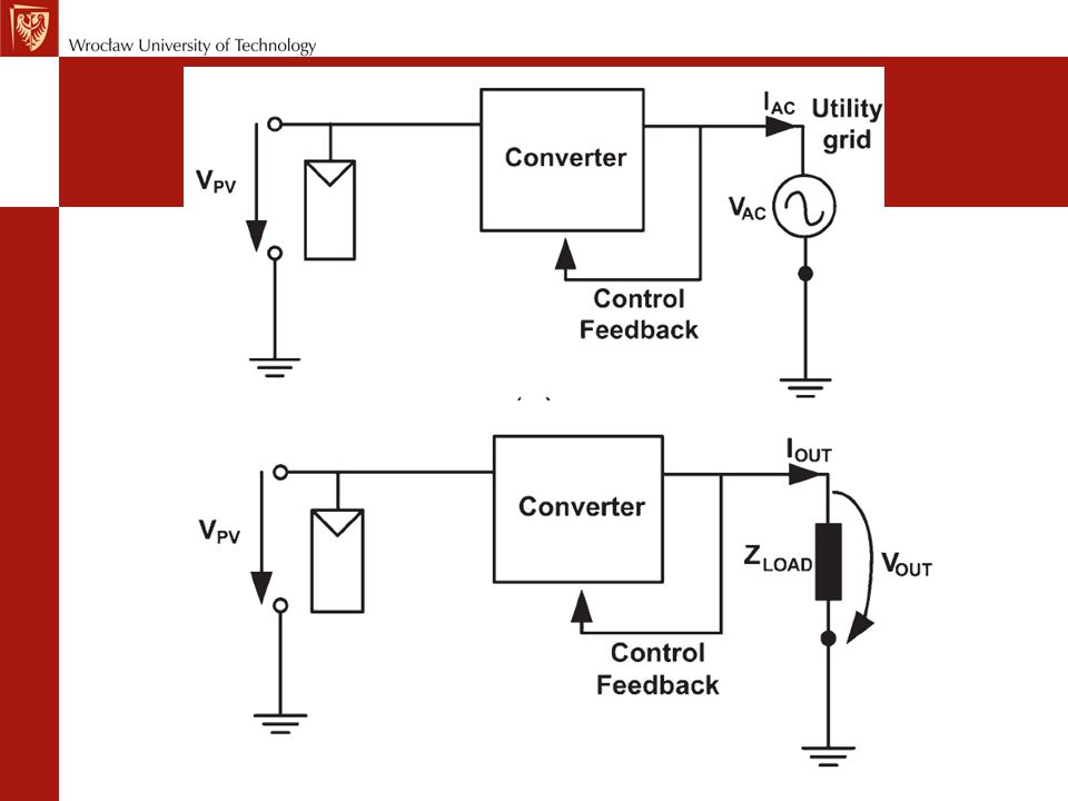


>")


