Download presentation
Presentation is loading. Please wait.

1
Connie Gomez, M. Fatih Demirci, Craig Schroeder
Unit Cell Characterization, Representation, and Assembly of 3D Porous Scaffolds Connie Gomez, M. Fatih Demirci, Craig Schroeder Drexel University 4/11/05

2
Outline Quick Summary of Project Earth Mover’s Distance (EMD)
")
3
Problem Statement Develop a framework to assemble biocompatible unit cell structures that mimic tissue properties to serve as a scaffold. ? Unit Cell Structures

4
Design Considerations
Informatics Possible Design Solutions 1) Mechanical requirements: scaffold structural integrity internal architectural stability scaffold strength and stiffness E & EEff G & GEff ν α ρ φS dpore Apore biomaterial selection internal architecture porosity and pore distribution fabrication method 2) Biological requirements: cell loading, distribution, and nutrition cell attachment and growth cell-tissue aggregation and formation dpore Apore θpore φS φFC layout pore size and interconnectivity; vasculature 3) Geometrical requirements: anatomical fitting L w h l φS θpore dpore Apore scaffold external geometry interconnectivity permeability selection φS φFC Apore k P V T μ ρ D Re 4) Transport requirements: nutrient and oxygen delivery waste removal drug delivery
 Mechanical requirements: scaffold structural integrity. internal architectural stability. scaffold strength and stiffness. E & EEff. G & GEff. ν. α. ρ. φS. dpore. Apore. biomaterial selection. internal architecture. porosity and pore distribution. fabrication method. 2) Biological requirements: cell loading, distribution, and nutrition. cell attachment and growth. cell-tissue aggregation and formation. dpore. Apore. θpore. φS. φFC. layout. pore size and interconnectivity; vasculature. 3) Geometrical requirements: anatomical fitting. L. w. h. l. φS. θpore. dpore. Apore. scaffold external geometry. interconnectivity. permeability selection. φS. φFC. Apore. k. P. V. T. μ. ρ. D. Re. 4) Transport requirements: nutrient and oxygen delivery. waste removal. drug delivery.")
5
Overview of Approach Preprocessing Initial Assembly
Unit Cell Characterization Application Requirements Initial Assembly Using a Given/Reference Unit Cell(s) Aligning Current Assembly with the Database Unit Cells Adding to the Assembly + Unit Cell Rotation Vector Update Heterogeneous Scaffold and Implant Design
 Aligning Current Assembly with the Database Unit Cells. Adding to the Assembly. + Unit Cell Rotation. Vector Update. Heterogeneous Scaffold and Implant Design.")
6
Informatics: Mechanical
Scaffold Material Properties Effective Young’s Modulus (EEff) Effective Shear Modulus (GEff) Poisson’s Ratio (ν) Coefficient of Expansion (α) Contour/Fluid Properties Diffusion Constant (D) Viscosity (μ) Density (ρ) Permeability (k)
 Effective Shear Modulus (GEff) Poisson’s Ratio (ν) Coefficient of Expansion (α) Contour/Fluid Properties. Diffusion Constant (D) Viscosity (μ) Density (ρ) Permeability (k)")
7
Informatics: Structural
Porosity/Volume Fraction Scaffold Material(φS) Contour/Fluid Material(φF) Effective/Open Porosity(φFC) Dead/Closed Porosity (φFD) Pore Size (dpore) Pore Area (Apore) Pore Angle (θpore)
 Contour/Fluid Material(φF) Effective/Open Porosity(φFC) Dead/Closed Porosity (φFD) Pore Size (dpore) Pore Area (Apore) Pore Angle (θpore)")
8
Informatics: Transport
Mass/Fluid Flux normal to surface (m) Velocity (u, v, w) Pressure (P) Geometric Tortuosity (T)
 Velocity (u, v, w) Pressure (P) Geometric Tortuosity (T)")
9
Model for Transport Characterization
Create model of pore space Unit Cell Length (L) Length of pore (l) Height of pore (h) Width of pore (w) Diameter of pore (dpore) Area of pore (Apore) Pore angle (θpore)
 Length of pore (l) Height of pore (h) Width of pore (w) Diameter of pore (dpore) Area of pore (Apore) Pore angle (θpore)")
10
Transport Characterization Input
Define fluid properties Density (ρ) Viscosity (μ) Specific Heat Define flow parameters Velocity Magnitude Velocity Direction Turbulent or Laminar Check Re Define boundary conditions Inlets Outlets Walls
 Viscosity (μ) Specific Heat. Define flow parameters. Velocity Magnitude. Velocity Direction. Turbulent or Laminar. Check Re. Define boundary conditions. Inlets. Outlets. Walls.")
11
Results for the given properties and flow parameters
CFD Analysis Mesh Model Run Analysis Nodal Information Node Coordinate and number Velocity (u, v, w) Pressure Surface Meshing: 2570 shells Volume Meshing:18442 cells Results for the given properties and flow parameters
 Pressure. Surface Meshing: 2570 shells. Volume Meshing:18442 cells. Results for the given properties and flow parameters.")
12
Unit Cell Representation
Common Engineering Representations CAD STL IGES Disadvantages: Not suitable for computing unit cell connectivity Complexity of optimization increases as the size of the scaffold increases We can not associate properties using these representations. Any operations that we do using skeletons cost much less than these common engineering representations. Rotation for example.

13
Skeletonization Skeleton:
An intuitive representation of shape and can be easily understood by the user, providing more control in the alignment process. Captures the topology of an object in both two and three dimensions.

14
Skeletonization – Example:
(x, y, radius)
")
17
Skeletonization – Example:

19
Skeletonization – Example:

20
Modified 2D Skeletonization
Set of skeleton points Coordinates and the radius of the circle used to find the skeleton point (x, y, z, r) Layering Three directions
 Layering. Three directions.")
21
Skeleton Point and Nodal Point Superposition
Skeletal Points Coordinates Radius Nodal Points Property Values at nodal point Velocity (u, v, w) Pressure
 Pressure.")
22
Property Calculation r=6.7
The nodal points can be associated with different cross sections.

23
Property Assignment Expansion of the skeleton representation
Original Skeleton Point Unit Cell 1: [ x, y, z, r] Layered in three directions for rotation Expanded Skeleton Point of the Pore Material Unit Cell 1: [x, y, z, r, p1, p2, …pn] Properties (normal to the surface) P1: Density P2: Velocity Magnitude P3: Positive/Negative Direction P4: Pressure P5: Flow Rate P6: Permeability
 P1: Density. P2: Velocity Magnitude. P3: Positive/Negative Direction. P4: Pressure. P5: Flow Rate. P6: Permeability.")
24
Overview of Approach Preprocessing Preprocessing Initial Assembly
Unit Cell Characterization Application Requirements Preprocessing Unit Cell Characterization Application Requirements Initial Assembly Using a Given/Reference Unit Cell(s) Aligning Current Assembly with the Database Unit Cells Adding to the Assembly + Unit Cell Rotation Update Vectors Heterogeneous Scaffold and Implant Design
 Aligning Current Assembly with the Database Unit Cells. Adding to the Assembly. + Unit Cell Rotation. Update Vectors. Heterogeneous Scaffold and Implant Design.")
25
Unit Cell Assembly (Alignment)
Framework to provide a structural and/or contour connectivity between unit cells The goal : To develop an approach that will assemble characterized unit cell structures into a larger heterogeneous scaffold

26
Assembly Given the volume (anatomical geometry) Bottom Up Approach
Starts from a unit cell at a given location within the volume with only a primary direction Top Down Approach Starts with two unit cells and a path to optimize. Goal is to provide transport connectivity for one of the parameters on this path.

27
Bottom-Up Approach Assemble a scaffold given constraints
A reference unit cell Outer scaffold geometry Direction for flow Three step assembly Assemble the unit cells along the primary direction Grow the line of unit cells in a second direction to form plane, starting from the reference unit cell Grow plane of unit cells in the third direction, starting from the reference unit cell

28
Bottom-up Approach Radius and Velocity.

29
Bottom-Up Assembly

30
Top-down Approach Assemble a scaffold given constraints
A path along which optimal flow is desired Fixed connections at either end of the path Outer scaffold geometry Two step assembly Construct the path, filling in cells along the path so as to minimize total discontinuity between cells Fill in the rest of the scaffold, choosing cells that minimize discontinuity

31
Top-down: Path Filling
Choose cubes and orientations for each cell in the path Minimize total discontinuity between adjacent cells along the path Illustration: filled path as part of a scaffold

32
Top-down: Scaffold Filling
Choose cubes and orientations for each remaining cell Fill from the path outwards Choose best fit Illustration: filled scaffold with path highlighted

33
Bottom-Up Approach using area

34
Top Down: Example using area

35
Top Down: Example using pressure

36
Summary Unit cell informatics, necessary for unit cell alignment, have been set forth. Unit cell characterization approaches have been outlined. The unit cell’s geometry has been reduced to a skeletal representation to reduce complexity. Top-down and bottom-up approaches have been used to create an assembly inside a 3D volume.

37
Earth Mover’s Distance (EMD)
Measure of dissimilarity between two sets of elements How much “work” is required to turn the first set into the second set

38
Earth Mover’s Distance (EMD)
Given Two sets of elements Some way to determining how dissimilar two elements are Result A measure of how dissimilar the two sets are

39
EMD Usage EMD takes two sets of elements
The elements are the skeleton points The elements include the properties attached to the skeleton points The sets of elements are the skeletons

40
EMD Usage EMD needs some way to determine how dissimilar two elements are Skeleton points differ by position Apos, Bpos Dissimilarity(A, B) = Distance(Apos, Bpos) Attributes are taken into account later This is called Ground Distance; EMD uses this
 = Distance(Apos, Bpos) Attributes are taken into account later. This is called Ground Distance; EMD uses this.")
41
EMD Usage A match between two skeleton points
A dissimilarity: Distance(Apos, Bpos) An amount of attribute being matched: a Cost of match: Distance(Apos, Bpos) * a A match between two skeletons A set of matches between skeleton points All of the attribute of skeleton has been associated with skeleton points from the other skeleton Total cost of all matches is minimal
 An amount of attribute being matched: a. Cost of match: Distance(Apos, Bpos) * a. A match between two skeletons. A set of matches between skeleton points. All of the attribute of skeleton has been associated with skeleton points from the other skeleton. Total cost of all matches is minimal.")
43
EMD for Alignment

44
Computing the best arrangement

46
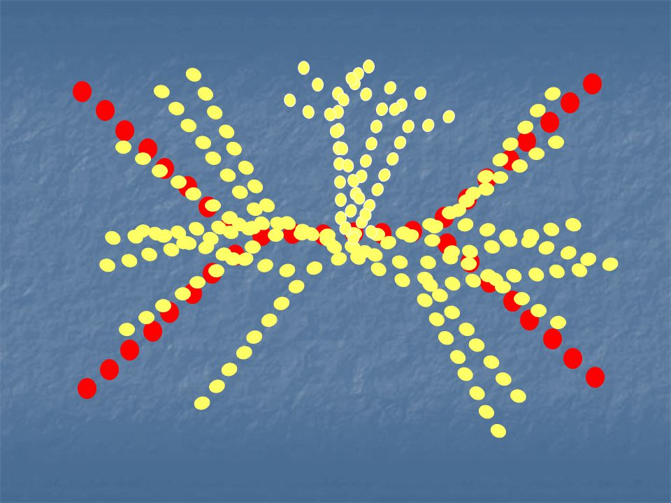
Example Two skeletons to compare Circle Rectangle

47
One Match One match between skeleton points

48
Attributes and Work All matches
Attribute of each node spread across the arrows Cost of each arrow is the length of the arrow times the amount of attribute assigned to it “Force” required to move that much attribute This distance times “force” is where the notion of “work” comes from Total “work” is minimized

49
Not One-to-One Note that some skeleton points have no arrows touching them There is more of this attribute in the red skeleton Not all of the red points have room to match with green All of green points match with one or more red points Note that others have multiple arrows touching them Green or red nodes These nodes have more of the attribute than what they are paired with Multiple arrows, total, contain the full amount of the attribute of that node

50
Why EMD? Known to be suitable in other domains
Object Recognition Who else uses this? Allows partial matches in a natural way Two skeletons might not match up exactly Partial matches make the comparison more flexible What else goes here?

51
Simple Example Do we need some sort of illustration(s) that show a small example of EMD step by step? Better idea of what is going on EMD process hard to visualize – linear programming problem Simplex method? Example How many nodes? Should they be complete scaffolds? Should they be labeled with attributes? Should they be labeled with coordinates? Should costs be computed and shown per edge? Should the cost be computed and shown for the whole thing? Should the optimal and a suboptimal match be shown for comparison? Does he need to see this example through all stages of the pipeline? Probably a lot of work! He seems to be okay with the other parts of the process Questionable benefit in understanding EMD

52
Questions

Similar presentations


 Create the geometry and the flap Sequence of.>")


