Download presentation
Presentation is loading. Please wait.

1
ATI ProCharger P1SC-1 (Tuner Kit) Installation
2004 GTO ATI ProCharger P1SC-1 (Tuner Kit) Installation
 Installation.")
2
Disclaimer The following information documents my personal ATI ProCharger installation experience. The comments made or suggestions are in no way intended to supersede or invalidate the ATI Assembly manual. Please refer to the ATI Assembly manual for your installation. However as to the “order” or “Sequence” of Installations, this overview might lend a little guidance.

3
Boxes Arrive 2 smaller boxes are banded together. The larger of the two is the ATI provided radiator fan shroud and hardware. The other box is the 16.5” SPAL radiator fan. All other kit components are contained in the large box

4
Inventory Begins The “BIG” box should contain
PC050A-40: P1SC-1 S/C /oil / misc. hardware. 3GNBB-01: Brackets / fastener bag. ATI Crank Pulley Assy. 3GNSS-01: Surge System. 3GNAI-01: Air inlet. 3GKMM-04: Crankshaft Pin kit. 3GNCR-01: ECM Relocation Kit. 3GNPS-01: Power Steering Relocation Kit. 3GNMM-01: Misc. 3GNMM-04: Cooling fan sys. 3GNMM-02: Cooling Sys. 3GNIC-01: Intercooler rubber and hardware kit. Intercooler and Induction sys. Owners manual / License frame / Decals

5
3GNCR-01 Computer Relocation Kit

6
3GNMM-04 New Radiator Fan Shroud and attaching hardware.
Also associated with this kit #, is the SPAL 6.5” fan located inside the “big” box.

7
3GNBB-01 Bracket and Fasteners For blower mounting

8
3GNMM-01 Miscellaneous Misc. tie wraps, wire splices, check valve, vacuum cap, vacuum hose, MAF extension.

9
3GNMM-02 Cooling System ATI thermostat housing, upper and lower radiator hoses, couplers, hose clamps, etc.

10
3GNPS-01 Power Steering Reservoir Relocation Kit
I had to modify the bracket as the ATI supplied bracket latch simply would not work.

11
Inventory Continues ME001G-1: oil 3GKMM-04: crankshaft pinning kit
3GNSS-01: Surge system and vacuum manifold

12
Blower Belt

13
P-1SC-1

14
P1SC-1

15
Crankshaft Pulley

16
Induction Tubing

17
Intercooler

18
Inventory Continues New K&N air intake filter.
Bag 3GNAI-01 contains misc. attaching hardware / anti chafe material for the air inlet system. No pic sorry Power Steering Cooler

19
Inventory Continues Billet Tower
Blower main bracket bolts up to this unit. This installs where the stock P/S reservoir was. Blower Oil 6 ounces

20
SPAL 6.5” and 16” Fans

21
Inventory Continues Assy. Manual Bill of Materials Free advertising

22
Inventory Complete Lets get going!!!

23
The Installation Begins

24
ProCharger Installation Sequence
To follow is the sequence of installation per the ATI procharger Assembly manual. In my opinion some time could be saved in altering the sequence to some degree. There are some items that are just in the way when trying to fit other systems. I will make my comments on the following pages, just remember that they are just my opinion!

25
ATI ProCharger Assembly Sequence
Remove gas cap to relieve press in fuel tank. (at least prior to fuel system mod) Remove fuel pump fuse. (same as above) Disconnect battery. (Definitely) Disconnect MAF (OK) Disconnect IAT (OK) Remove OEM Air box (OK) Remove Radiator cover (OK) Remove OEM Fan’s / Shroud (OK) Drain Coolant System (OK) Swap OEM thermostat housing with ATI housing. (OK) Remove Power Steering reservoir bracket. (OK) Remove Coolant Reservoir. (OK) Remove ECM / modify heat shield / install new brackets / relocate (sequence OK, see slides for modifications) Relocate power steering reservoir (OK)
 Remove fuel pump fuse. (same as above) Disconnect battery. (Definitely) Disconnect MAF (OK) Disconnect IAT (OK) Remove OEM Air box (OK) Remove Radiator cover (OK) Remove OEM Fan’s / Shroud (OK) Drain Coolant System (OK) Swap OEM thermostat housing with ATI housing. (OK) Remove Power Steering reservoir bracket. (OK) Remove Coolant Reservoir. (OK) Remove ECM / modify heat shield / install new brackets / relocate (sequence OK, see slides for modifications) Relocate power steering reservoir (OK)")
26
ATI ProCharger Assembly Sequence
Reinstall coolant reservoir: (wait until after Air Intake filter is fitted) Remove front Fascia, bumper, horns, and air dam. (OK) Installation of new injectors: (if you have the tuner kit, do this last) Crankshaft pulley “pinning” (sequence OK, see slides for my comments) Procharger / main bracket assemble. (OK) New fan shroud fitment / fan installation / fan wiring mods / install in car: (fit shroud, install fans, install in car, mod wiring) Cooling system mods / upper and lower hoses and tubes: See slides for my input Intercooler / induction tubing and anti surge system install: See Slides Trim air dam Install new power steering cooler: (OK) Service coolant and power steering reservoirs: (wait until ready to start) Reinstall air dam / bumper / horns / and front fascia (not until all leak checks have been performed) Install Vacuum manifold / cap PCV vent line on TB / install ATI provided check valve / run vacuum line to air filter: See Slides Trim and reinstall radiator cover: (OK)
 Remove front Fascia, bumper, horns, and air dam. (OK) Installation of new injectors: (if you have the tuner kit, do this last) Crankshaft pulley pinning (sequence OK, see slides for my comments) Procharger / main bracket assemble. (OK) New fan shroud fitment / fan installation / fan wiring mods / install in car: (fit shroud, install fans, install in car, mod wiring) Cooling system mods / upper and lower hoses and tubes: See slides for my input. Intercooler / induction tubing and anti surge system install: See Slides. Trim air dam. Install new power steering cooler: (OK) Service coolant and power steering reservoirs: (wait until ready to start) Reinstall air dam / bumper / horns / and front fascia (not until all leak checks have been performed) Install Vacuum manifold / cap PCV vent line on TB / install ATI provided check valve / run vacuum line to air filter: See Slides. Trim and reinstall radiator cover: (OK)")
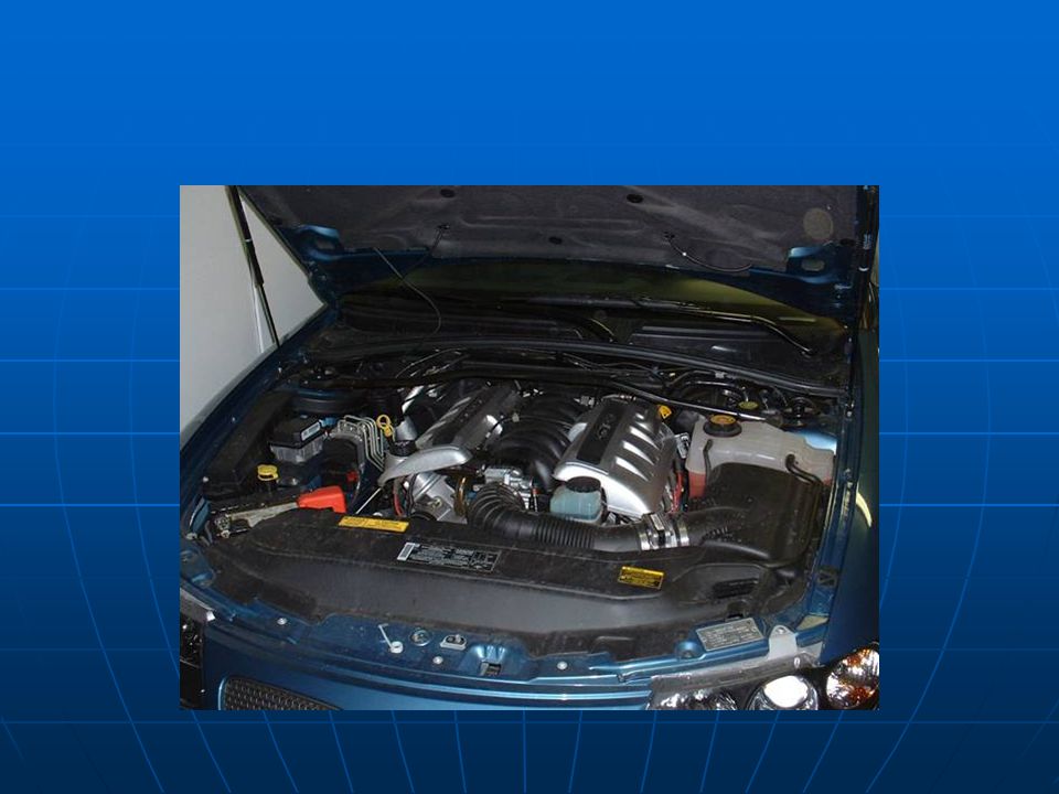
27
Stock…..But Not For Long

30
First Things first. Disconnect – battery terminal

31
Air Intake Removal MAF Prior to removing the air intake tube. The electrical connections to the MAF and the IAT sensors must be disconnected. Gently lift the locking tabs and separate the connectors IAT

32
Remove Factory Air Intake and MAF
Clamps

33
Remove Air Box OEM Filter Factory Air Box Air Box Removed
Forward inlet to be removed as well

34
Radiator Cover Removed

35
Radiator Fan Removal. Two connectors as shown supply power to the OEM Fans

36
There are 4 clips, 2 on each side, once loose the fan shroud lifts straight up

37
Drain Coolant from system
Remove lower radiator hose from Drivers side. Hopefully you have better aim than I did!!

38
Thermostat Housing Ensure that the “O” Ring squeezes between housing and block. If there is metal to metal contact something is wrong. ATI LS1 Block ATI OEM OEM

39
Power Steering Reservoir Relocation
OEM Location Remove Bracket Bracket Removed

40
Remove Coolant Tank Aft mounting Tank pulls from stud on fender
Disconnect Low level sensor

41
Engine Control Module Removal
Remove 7MM screws, pull harness away from ECM. Remove ECM from Car.

42
ECM Relocation Prep Locate parts bag 3GNCR-01
Remove the four corner screws from ECM Locate brackets and reinstall screws ECM will now be relocated aft of OEM position

43
ECM Heat Shield Modification
ECM heat shield gets trimmed by 5” A box cutter works fine for this. Make sure you cut the right end off! Once trimmed the Heat shield is mounted to the ECM.

44
ECM Relocation ECM bracket mounts to master brake cylinder housing.
Note wires are exposed . Although there is a good seal on the ECM connectors, there are too many liquids in this area to be content with no extra protection. I elected to modify and retain the OEM lid.

45
ECM Lid Modification *Not per ATI instructions
Cut 1” off bottom Added 1 washer Front and aft posts Drilled 4 small holes and Zip Tied to posts.

46
Power Steering Reservoir Relocation
P/S reservoir is now attached to the Brake booster. This is another area that did not go well. The ATI provided P/S bracket is of poor design. I modified by putting anti chafe strips on the side rails, removed the poorly designed lock tab in back, drilled two small holes through the reservoir mounting channel, and tie wrapped the Reservoir to the new bracket. While not happy with this set up either, at least the reservoir doesn’t pop off the bracket like it did!

47
Power Steering Reservoir Relocation
For some reason unknown to me, ATI splices a ½” hose onto the 3/8ths power steering fluid return line to the reservoir. I did not care for the appearance or trying to tighten a 1/2” line onto a 3/8ths plastic reservoir connector. I went to the auto supply store and purchased some 3/8ths” transmission hose. 3ft is more than enough. Return Supply

48
Front fascia Removal Be careful…..go slow….follow the directions. Even so I still managed to break a tab. According to the Assy manual super glue will fix it……..We shall see.

49
Front Access fascia Removal Horns Removal Bumper Removal
Front Air Dam Removal

50
Crank Pulley Installation
ATI does not have you remove the radiator for this project. I felt it was the best way to ensure proper drilling of the crankshaft Remove Radiator Loosen all A/C heat exchanger brackets, just follow the lines, remove any bracket hardware and lift lines out of brackets. lift exchanger out of position to expose crankshaft pulley. You do not need to loose any refrigerant. Do not break connections.

51
Crank Shaft Pinning Install Pinning Kit.
Drill using supplied drill bit. Do not drill deeper than the Pin length. When calculating how deep to drill, take into account the thickness of the Drill guide. Measure 3X drill once!!

52
Drilling completed, Install pin

53
ATI 8 Rib Pulley Concave portion of washer Goes towards crankshaft.
Note Pins on back of Pulley. These snug up against the factory pulley webbing…3 pts. Rotate Pulley CCW until pins contact OEM webbing then torque to specs. Engine runs CW, as viewed from front. The CCW position is to ensure the ATI pulley is being driven by the OEM pulley Concave portion of washer Goes towards crankshaft.

54
Optional Fluidampr Installation Due to belt alignment issues I recommend this option. It will also allow for higher boost later on. You will need to pull the OEM Pulley from the crankshaft. Install the Fluidampr per instructions. Pin the Fluidampr / crankshaft per ATI instructions

55
Crank Pinning tool installed
Measuring how deep to drill Crank Pin installed New Torque to Yield crank bolt

56
Cooling System Once the Crankshaft pulley is installed the A/C heat exchanger and Radiator may be reinstalled. During this process pay attention to the lower cooling system mods that will be done. It will be easier to refit the coolant transfer tubes with the radiator removed. However to ensure proper clearances you may have to temporarily install the radiator make your measurements, remove radiator and install the lower coolant transfer system. Sounds complicated….its not!

57
ATI Radiator Fan Shroud
Prior to installing the new SPAL fans, the retention brackets need to be fitted. They are specific to LFT and RT. The shroud should fit flush with the radiator…mine did not. I had to modify the bracket locations to ensure a snug fit to the radiator

58
ATI Fan Shroud Installation
Had the slots run the other Way I would have been OK Round holes Are new ones I drilled Bracket install

59
Only after the shroud has been fit to the radiator should you mount the 16” and 6.5” SPAL fans. Once the fans are mounted the assembly can be installed in the car. The wiring mods can be done with the fan shroud installed. It will be easier to determine how much wire lead to cut with the assembled fan shroud installed in the car.

60
Heater Core Return to Coolant tank Mod *Not per ATI
The Kit provided lower radiator hose is a brass hose mender to lengthen and join the heater return hose to the coolant tank. I opted to modify the OEM coolant transfer tube. I should have looked at this prior to reinstalling the radiator, as there is easy access to this area with the radiator out of place. In any case use your best judgment for maintenance friendly installation. With a little advance planning you may be able to modify the entire OEM system

61
Lower Radiator Hose The lower hose connects from the thermostat housing via a new steel transfer tube. The other end of the transfer tube connects to the lower radiator fitting. New Transfer tube

62
Lower Cooling System *Modified from ATI
OEM heater transfer tube (previously modified) ATI provided Lower tube ¾” Adel clamp: 2 ea 1 3/8” Adel clamp: 2 ea.
 ATI provided Lower tube. ¾ Adel clamp: 2 ea. 1 3/8 Adel clamp: 2 ea.")
63
Upper Radiator Hose Utilizes an ATI supplied coupler and new preformed section to wrap around the Induction tube New hose Coupler

64
Cooling System Just a piece of advice, do not service cooling system until the very end of the project. During the process of the rest of the install I had to remove portions of the system several times. No sense in losing expensive coolant if you don’t have to!

65
Time To Mount the Head Unit

66
ProCharger Mounting.

67
Head Unit Assy. Locate Bag 3GNBB-01 Protect inlet and discharge ports

68
Mount Head Unit to Bracket Per Instructions, Torque values can be found at the beginning of the assy. manual

69
Blower Installation Billet Tower gets installed in the original P/S reservoir location. Main bracket is held in place by a stud that replaces a bolt under the P/S pump pulley and these three bolts A Billet spacer will be installed containing the top to bolts later, mine was shorted from the kit Billet Tower

70
Install Blower Belt Failure to ensure belt alignment will produce the same results as shown below. Simply eyeballing is not enough. Remove belt tensioner and use a straight edge to ensure alignment. If there is a problem call ATI for guidance.

71
Pulley Alignment Check Remove belt tensioner system
Pulley Alignment Check Remove belt tensioner system. Use a straight edge to confirm pulley alignment Good BAD

72
Blower Belt Tensioning
Loosen lock bolt Loosen Lock nut Tighten brass tensioner nut to ATI specs Tighten Lock Bolt and Lock nut

73
Intercooler Installation
I kept the bubble wrap on as long as possible to help protect it from installation damage. Once installed my hood release was hitting the top of the intercooler. You can easily look down the opening in the radiator support to ensure clearance. To adjust clearance simply modify the top bracket to pull the intercooler in or to push it out.

74
Intercooler Installation
The intercooler will utilize the OEM P/S cooler mounts. Step 1: Remove the P/S cooler…Plug lines! Step 2: Remove P/S cooler brackets Step 3: Install ATI upper and lower I/C brackets on I/C Step 4: Mount ATI brackets to the OEM P/S brackets Step 5: Install I/C in car

75
Intercooler Installation
Locate Bag 3GNIC-01 This bag contains hardware and ducting couplers.

76
Intercooler mounting Modification
Since we are adding quite a bit of mass to the stock P/S cooler brackets. I removed the sheet metal screws and installed Stainless steel 10x32 screws with lock nuts. To accomplish this I had to drill 2ea. 1” holes for access to the hardware. 1” holes for access

77
Intercooler mounted…Induction tubing fitting begins

78
Induction Tubing Modification
Once the induction tubing was installed. I thought it was too flexible. I was concerned about the possibility of a duct coupler vibrating off. I decided to clamp the ducts in 5 locations

79
Induction Tubing Clamps
As I could not find 3” Adel clamps, I simply made my own. I utilized 1/16th by 3/4” aluminum stock found at the home improvement store. I then purchased some shower/bath PVC underlayment to utilize as an anti chafe strip. Which was trimmed and glued to the clamp with 3M 77 adhesive. The clamps were made by simply hand forming around a 3” section of induction tubing and gluing a piece of anti chafe material with the M77 adhesive

80
Induction Tubing Clamps Continued

81
The clamps greatly stabilized the induction system, yet retains some needed flexibility.

82
Clamp Mod Continued

83
More Tubing MAF new location

84
Induction tubing

85
Surge Valve Installation
Added clamp for stability Drivers side forward of wheel well

86
Vacuum Manifold Installation
Back of intake Manifold Vacuum line run to Surge Valve Brake booster end

87
Power Steering Cooler

88
Miscellaneous Install cap removed from Drivers side to Pass side.
Check valve installed flow Drivers side head, remove Vacuum plug. 3/8 hose runs From here to Intake air filter PCV Vent line removed Install supplied cap

89
K&N Air Intake Filter Installation

90
The Intake filter gets 2 holes drilled
The Intake filter gets 2 holes drilled. 1 for the IAT sensor and 1 for the vacuum line. Do not assume the hole size quoted in the manual is correct, measure the sensor to determine proper hole size!!

91
The rubber connector will need to be trimmed
The rubber connector will need to be trimmed. Have the coolant reservoir nearby as you must fit the induction tube to clear the reservoir. Vacuum line IAT Sensor Rubber connector Coolant Reservoir Location

92
Wiring Harness I installed an ½” Adel clamp on the blower, the harness pretty much fell into place from there. I ran the MAF extension under the throttle body instead of along the radiator shroud.

93
Trim Radiator Cover

94
Now I Serviced everything and fired her up
Now I Serviced everything and fired her up. I had a nightmare with belt alignment and decided to chuck the OEM pulley and install the fluidampr. This set up will allow for higher boost levels in the future, as well as solve my belt alignment issues now.

95
Bumper Modification I got this Idea from Bob at Exotic Performance Plus. The OEM crash bar really prevents good airflow through the intercooler.

96
I marked where the bumper interfered with the intercooler airflow and cut the back and lower sides. From the front you can’t tell it was cut!

97
With the bumper cut, I was a little concerned about the strength that was removed. So I decided to do an old hot rodder frame mod, and “box” in the cut out section.

98
I went to a local steel supply shop and procured some scrap 16 ga
I went to a local steel supply shop and procured some scrap 16 ga. Then I simply made templates, transferred them to the steel, and cut them out.

100
Welding completed

101
Trial Fit

102
A little body work

103
Painted

104
With the lower air dam installed this should be a substantial airflow improvement.

105
Final Bumper Install Styrofoam needed to be trimmed

106
Air Dam Trimming Wait until final fitting of induction tubes and bumper installation. As you can see I got a little carried away with the passenger side because trimming started before final fitting was accomplished!! It is much easier to visualize what and where to trim with the bumper in place.

107
Final Install After the bumper Mod. The front end was closed out.
Install bumper Install horns Install front Fascia Install radiator cover

108
Fuel System Not covered is the fuel injector change and associated tuning. As this is more of an LS1 issue, and not specific to the ATI installation, I have not included it on this presentation. There are many data sources available to document this install.

109
Installation Complete!!

Similar presentations


>")


