Download presentation
Presentation is loading. Please wait.

1
Television 1 Jess Role @ UEAB2006 Video IF Amplifier

2
Television 1 Jess Role @ UEAB2006

3
Three parameters considered as waveform for Video IF amplifiers Amplitude Amplitude Frequency – when the amplitude and the frequency are displayed it is called frequency domain displayed Frequency – when the amplitude and the frequency are displayed it is called frequency domain displayed Time – when the amplitude and time are displayed it is called time domain display. Time – when the amplitude and time are displayed it is called time domain display.

4
Television 1 Jess Role @ UEAB2006

5
Intermediate frequency 41.25 MHz Video free interference frequency 41.25 MHz Video free interference frequency 41.25 Sound free from possible interference frequency 41.25 Sound free from possible interference frequency Tuned to 25.75 MHz and 21.5 MHz oscillator frequency range from 80 MHz to 212 MHz Tuned to 25.75 MHz and 21.5 MHz oscillator frequency range from 80 MHz to 212 MHz Falls on channel 5-13 Falls on channel 5-13

6
Television 1 Jess Role @ UEAB2006 IF Stage Sound takeoff is obtained from the last IF amplifier and is feed to a separate sound IF detector Sound takeoff is obtained from the last IF amplifier and is feed to a separate sound IF detector Today’s sound takeoff points occurs in the video IF Stage Today’s sound takeoff points occurs in the video IF Stage

7
Television 1 Jess Role @ UEAB2006

8
Four Major Function of Video IF Strip To compensate for vestigial sideband transmission To compensate for vestigial sideband transmission To provide the most of the selectivity required by the receiver for interference- free reception To provide the most of the selectivity required by the receiver for interference- free reception To provide most of the picture and sound signal amplification of the receiver To provide most of the picture and sound signal amplification of the receiver To frequency change the IF into the video signal at the video detector To frequency change the IF into the video signal at the video detector

9
Television 1 Jess Role @ UEAB2006

10
IF Response 45.75 MHz the desired IF signal produced at the picture IF carrier 45.75 MHz the desired IF signal produced at the picture IF carrier 41.25 MHz for the sound IF carrier 41.25 MHz for the sound IF carrier Upper adjacent picture at 39.75 MHz Upper adjacent picture at 39.75 MHz Lower adjacent sound carrier at 47.25 MHz Lower adjacent sound carrier at 47.25 MHz

11
Television 1 Jess Role @ UEAB2006 Inter-carrier Buzz Misalignment can cause excessive amplitude modulation at 4.5 MHz Misalignment can cause excessive amplitude modulation at 4.5 MHz Possible loss of sound and picture carriers may result to a 60 Hz rate of the vertical sync pulse Possible loss of sound and picture carriers may result to a 60 Hz rate of the vertical sync pulse Inhibition from AM signal is not completed that can cause or may result to Buzz signal Inhibition from AM signal is not completed that can cause or may result to Buzz signal

12
Television 1 Jess Role @ UEAB2006 Compensation for Vestigial sideband Transmission Three signal components Three signal components Lower sidebands extend to 1.25 MHz bellow the carrier Lower sidebands extend to 1.25 MHz bellow the carrier Upper sidebands extend 4.2 MHz above the carrier Upper sidebands extend 4.2 MHz above the carrier Partial sideband called Vestigial Partial sideband called Vestigial

13
Television 1 Jess Role @ UEAB2006

14
Color Receiver IF response The Video Sound IF The Video Sound IF The picture IF The picture IF Upper and lower Sidebands associated with the black and white or luminance signal: these signal range from 0.75 MHz bellow the carrier to 4.2 MHz above the picture carrier Upper and lower Sidebands associated with the black and white or luminance signal: these signal range from 0.75 MHz bellow the carrier to 4.2 MHz above the picture carrier

15
Television 1 Jess Role @ UEAB2006

16
Video IF traps Reduce Video IF response by means of highly selective resonant filters Reduce Video IF response by means of highly selective resonant filters

17
Television 1 Jess Role @ UEAB2006 Common types of Traps Series resonant shunt traps – mild short circuiting Series resonant shunt traps – mild short circuiting Parallel resonant series traps – signal path blocking Parallel resonant series traps – signal path blocking Transformer traps- filtering through magnetic induction using the secondary as the output Transformer traps- filtering through magnetic induction using the secondary as the output Absorption traps – eliminating undesired signal Absorption traps – eliminating undesired signal Bridge T traps – using resistors by determining the amount of attenuation Bridge T traps – using resistors by determining the amount of attenuation

18
Television 1 Jess Role @ UEAB2006

19
Television Video IF requirements Over-couples tuned transformer- primary and secondary with a degree of mutual coupling adjusted to exceed critical coupling Over-couples tuned transformer- primary and secondary with a degree of mutual coupling adjusted to exceed critical coupling Bifilar transformer- unity coupling Bifilar transformer- unity coupling Loaded tuned circuits- using loading resistor to balance the circuit Loaded tuned circuits- using loading resistor to balance the circuit Synchronous tuning- tuned circuit with the same frequency Synchronous tuning- tuned circuit with the same frequency Stagger tuning – obtaining a wide band-pass amplifier synchronizing other amplifiers Stagger tuning – obtaining a wide band-pass amplifier synchronizing other amplifiers Walking IF- adjustable bandpass circuit Walking IF- adjustable bandpass circuit Surface acoustic wave (SAW) filters – using piezoelectric materials to maintain a specific frequency Surface acoustic wave (SAW) filters – using piezoelectric materials to maintain a specific frequency
 filters – using piezoelectric materials to maintain a specific frequency Surface acoustic wave (SAW) filters – using piezoelectric materials to maintain a specific frequency")
20
Television 1 Jess Role @ UEAB2006

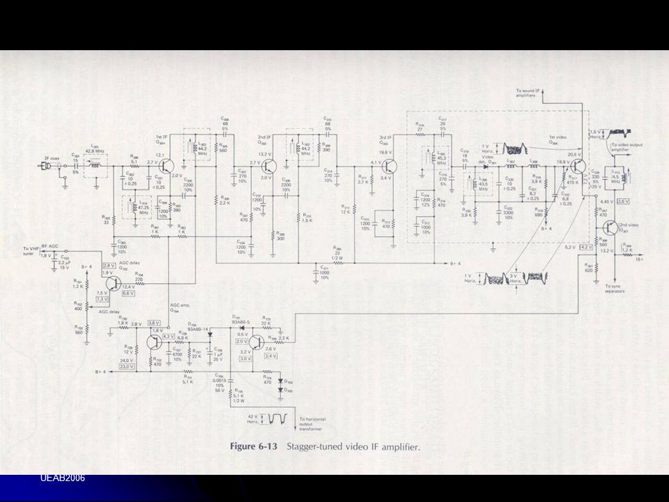
21
Transistor Video IF using Impedance coupling between stages

22
Television 1 Jess Role @ UEAB2006

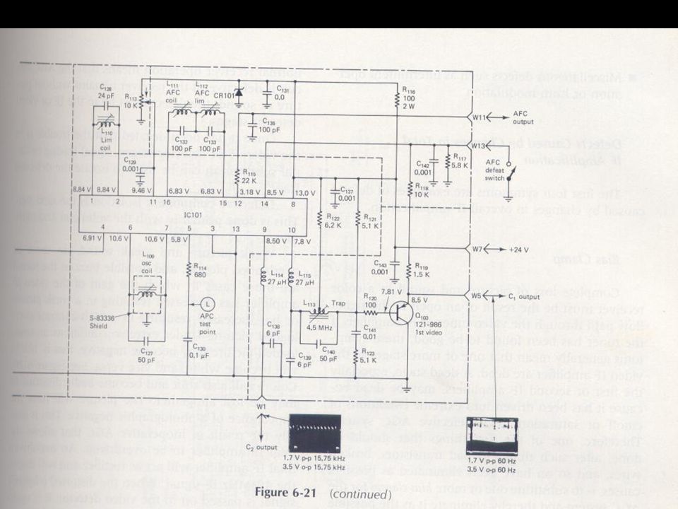
25
IC Video Amplifier

26
Television 1 Jess Role @ UEAB2006 Equipment needed for Sweep Alignment Consider Manufacturers alignment service manuals Consider Manufacturers alignment service manuals Make sure that SG has an accurate marker combination Make sure that SG has an accurate marker combination An oscilloscope can cope with low frequency at low level An oscilloscope can cope with low frequency at low level Matching pads- terminate SG 75 ohms transmission line Matching pads- terminate SG 75 ohms transmission line Bias supplies- AGC bias clamps etc Bias supplies- AGC bias clamps etc Demodulator probes- using manufactures alignment manuals observing frequency response Demodulator probes- using manufactures alignment manuals observing frequency response

27
Television 1 Jess Role @ UEAB2006 Video Alignment hookup

28
Television 1 Jess Role @ UEAB2006 B/W Video detector is consist of the following The composite video signal (0 to 4.2 MHz The composite video signal (0 to 4.2 MHz 4.5 MHz sound IF 4.5 MHz sound IF A dc Component corresponding to the average illumination of the picture A dc Component corresponding to the average illumination of the picture Residual IF and higher-frequency harmonic comonents Residual IF and higher-frequency harmonic comonents

29
Television 1 Jess Role @ UEAB2006 Video detector Used in Black and White

30
Television 1 Jess Role @ UEAB2006

31
Video detector used in Color Television

32
Television 1 Jess Role @ UEAB2006 Troubleshooting Video IF problems No picture no sound raster ok No picture no sound raster ok No picture sound ok raster ok No picture sound ok raster ok Weak color and black and white picture, weak sound, raster ok Weak color and black and white picture, weak sound, raster ok Overloaded or negative picture buzz sound raster ok Overloaded or negative picture buzz sound raster ok Inter-carrier buzz in sound Inter-carrier buzz in sound Poor vertical and horizontal synchronization Poor vertical and horizontal synchronization tunable ringing or oscillation in the picture tunable ringing or oscillation in the picture

33
Television 1 Jess Role @ UEAB2006

36
Continuation Smeared picture Smeared picture Sound bars in picture Sound bars in picture Poor color fit Poor color fit No color No color Best color and best black and white have different fine tuning position Best color and best black and white have different fine tuning position Hum in the picture Hum in the picture Intermittent deffects Intermittent deffects

37
Television 1 Jess Role @ UEAB2006 Possible causes Defects caused by an increase or decrease in total amplification of the Video IF Defects caused by an increase or decrease in total amplification of the Video IF Defects caused by changes in alignment Defects caused by changes in alignment Other defects such as intermittent operation or hum modulation Other defects such as intermittent operation or hum modulation

38
Television 1 Jess Role @ UEAB2006 Solving some issues in the Video IF Using Bias Clamp – variable power supply that is placed across the output of the AGC system Using Bias Clamp – variable power supply that is placed across the output of the AGC system Use plastic precision tools in adjustment (incase adjustment is tampered) Use plastic precision tools in adjustment (incase adjustment is tampered)
 Use plastic precision tools in adjustment (incase adjustment is tampered)")
39
Television 1 Jess Role @ UEAB2006 Common causes of Intercarrier Buzz Defective transistor or IC Defective transistor or IC Overload signal Overload signal Misadjusted traps Misadjusted traps Improper alignment of Video IF stage Improper alignment of Video IF stage Overload IF amplifiers Overload IF amplifiers Hum modulation of the signal Hum modulation of the signal Misalignment causing poor low frequency signal Misalignment causing poor low frequency signal

40
Television 1 Jess Role @ UEAB2006 Causes of regeneration and oscillation Defective transistor Defective transistor Open decoupling and bypass capacitors Open decoupling and bypass capacitors Open or change value neutralizing capacitors Open or change value neutralizing capacitors Open damping resistors Open damping resistors Open or shorted AGC filter capacitors Open or shorted AGC filter capacitors Defective tuned circuits Defective tuned circuits Shields that have been removed or disconnected Shields that have been removed or disconnected Poor grounding connection Poor grounding connection Improper lead dress or component placement Improper lead dress or component placement Misalignment of video IF Misalignment of video IF

41
Television 1 Jess Role @ UEAB2006

Similar presentations


>")


 Transmitters>")


 ©2003 Glencoe/McGraw-Hill Charles A. Schuler.>")