Download presentation
Presentation is loading. Please wait.

1
Spring-Loaded Onager Presentation DustinJeremyRyan

2
Table of Contents ► Problem Identification Problem Identification Problem Identification ► Research and Investigation Research and Investigation Research and Investigation ► Create Possible Solutions 1 st Design 1 st Design – 2 nd Design – 3 rd Design 2 nd Design 3 rd Design 1 st Design 2 nd Design 3 rd Design ► Choose Best Solution Choose Best Solution Choose Best Solution ► Developmental Work/Analysis Developmental Work/Analysis Developmental Work/Analysis ► Construct a Prototype Construct a Prototype Construct a Prototype ► Test and Evaluation Test and Evaluation Test and Evaluation ► Other Research Other Research Other Research

3
Problem Identification Goal: To design and develop a machine capable of launching a projectile at a given target. The launcher needs to be capable of compensating for elevation changes, differences in angles and distances to strike a given target. Furthermore, it should be able to reset and move quickly and accurately for multiple moving targets. If possible the launcher should be able to reload and fire automatically, with no outside intervention. Return

4
Research and Investigation: Design Constraints ► Must be able to launch a distance between 5’ and 20’ ► All projectiles must weigh no more than 20 grams ► Any building materials are permitted (primarily K'nex) ► Cannot be shot higher than 10’ ► Must be accurate enough to hit an 8” target ► Must be durable enough to make multiple firings *NOTE: Other constraints were present at the beginning of the project; however due to problems and time constraints, they were removed in the interest of the class. Return

5
Create Possible Solutions 1 st Design: Counterweight Powered Drawn by Dustin McGehee Return

8
Create Possible Solutions 2 nd Design: Counter-Weight Onager Drawn by Ryan Beringause Return

10
Create Possible Solutions 3 rd Design: Traditional Tension Powered Onager Drawn by Jeremy Rosser Return

12
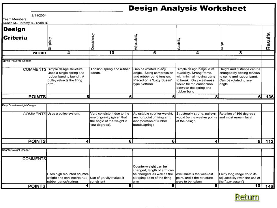
Choose Best Solution As a group we decided upon Dustin’s Counterweight design due to its simplicity, large range of adjustability, and ease of construction. Return ReturnReturn

14
Developmental Work/Analysis In our original design plans, we were to build a catapult with gravity as its primary propulsion. But after much testing, we concluded that a gravity powered engine was not possible due to the limits in size and weight. We found out that the K’nex could not withstand the pressures needed to propel the missiles as far as a spring powered design could. CLICK here to continue Return CLICK here to continue ReturnCLICK here to continue ReturnCLICK here to continue Return

15
Developmental Work/Analysis Table of Contents FRAME PROPULSION RELEASE MECHANISM MECHANISM PROJECTILE FIRING ARMFIRING ARM Return Return FIRING ARM Return

16
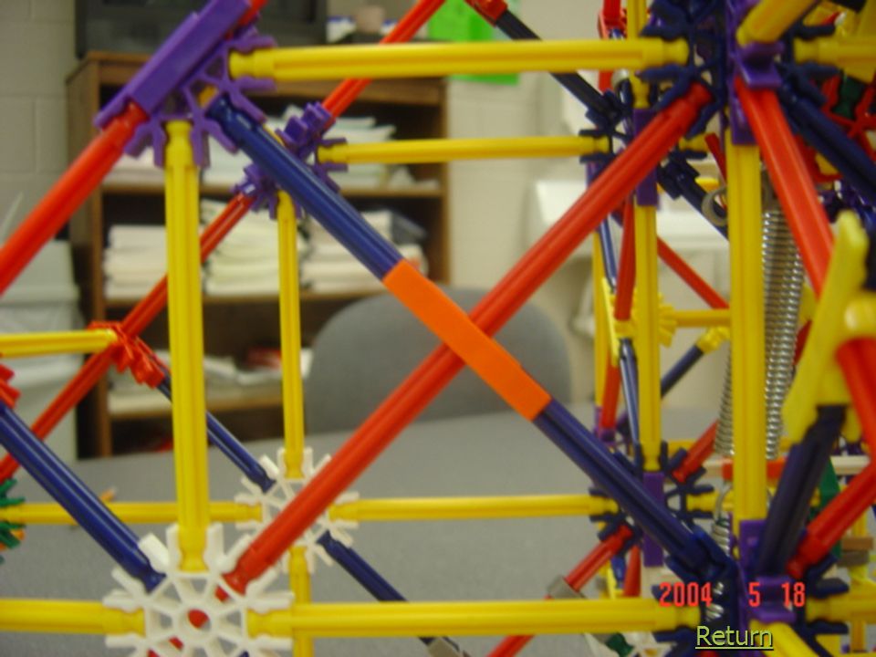
Frame Due to the extreme pressures applied by our design, we were forced to extensive modifications to the frame to strengthen it. We applied a basic design principle, by utilizing triangles throughout the frame. Return

20
Propulsion One of the problems we faced when we were developing our catapult, was with the propulsion system. To provide a better angle for the spring to be drawn, we made an attachment to keep this angle as close to 90 degrees as possible. To strengthen the lower attachment point for the spring, we dispersed the load by utilizing zip ties to apply the load to other anchor points Return

23
Release Mechanism ► As we began to develop our release mechanisms, we experienced to major problems. The first complication was the fact we had TOO MUCH power. The added strain applied such torque to the pulleys that we broke many parts trying to eliminate the slippage. The second problem we experienced resulted in the decision to build the current release design. Before, we used a design built solely out of K’nex. This in turn caused a problem when we would go to release it, since K’nex have many sides and angles. These angles caught on our paddlewheel and decreased the power we could have had. By watching the catapult, it would appear that it would hesitate before firing. CLICK Here to continue

24
Release Mechanism This piece of the design proved especially challenging to build due the fact that it must withstand the torque we require for firing. Initially, we began by using only K’nex as our spool. Yet as we increased the springs power, this design quickly failed. We then moved to a similar design where we soldered the five pieces together as one. This step proved to just be a temporary patch since we would later add more power to the catapult with stronger springs. Our current design is an evolution of the previous versions, where we have added two additional pieces to anchor the pulleys to the main axle. CLICK here to continue

25
Return

31
Release Mechanism To set the release mechanism, you must turn the paddlewheel counter clockwise until the arm has reached a desired power setting. We measure our power settings by the number of 1/8 of a rotation. To lock the arm, slide the Plexiglas bar into the paddlewheel. And to release it, pull the Plexiglas out and stand back. Return

32
Projectile As we built our catapult, we had originally decided upon using a clay ball as suggested by Mr. Grant. But as we began to test our siege engine, we found that clay balls quickly became brittle and were inconsistent when fired. With this, we began to think of an object that could replace the clay ball. After testing many possible projectiles, we found one that was as close to perfect as we could. We chose a rubber bouncy ball due to its compact size and added traction benefits. The only catch was it weighed 6.5 g to much. To reduce its mass, we bored various diameter holes through it. Eventually we reduced its weight to just under 20 g. It was not until later that we discovered that by removing the balls core, we also weakened it. CLIICK here to continue CLIICK here to continue

33
Projectile The Saboteurs STIKE!! During this project, we experienced many instances where our catapult was sabotaged. During the last case, someone destroyed our bouncy ball to the point it had broken into three pieces. To repair the ball, we had to pump hot glue back into its holes to secure the pieces from the inside. The only real downside to this matter is that we added back an additional 4 g. to our ball, putting us over the 20 g weight limit. Return

35
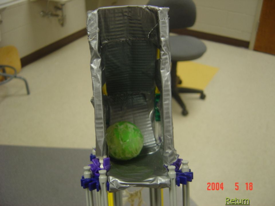
Firing Arm Another difficult piece to develop was the holder that we would place our projectile in. From the beginning we had envisioned a part resembling either a basket or cup, but as we progressed with the project we agreed upon a more radical design. To replace the basket, we created an arm with an attachment resembling a Jai Lai racket. With its curved shape, it helped accelerate the ball faster than before. The only problem was that the plastic we used to assemble it with was to flexible. To strengthen the plastic, we coated it with duct ape. Return

39
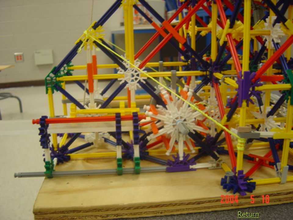
Construct a Prototype This is an example of our catapult at 100% power. It is being manned by Jeremy Rosser. Return

40
Test and Evaluation Return

43
Other Research Crank and Rod Crank and Rod (Dustin) Levers (Jeremy) Levers Crank and Rod Levers Simple Machine Project Simple Machine Project Rack and Pinion Rack and Pinion (Ryan) The Trebuchet (Dustin) Simple Machine Project Siege Engine Project The Trebuchet Rack and Pinion The Trebuchet The Magonel The Magonel (Jeremy) The Magonel Siege Engine Project
 Levers (Jeremy) Levers Crank and Rod Levers Simple Machine Project Simple Machine Project Rack and Pinion Rack and Pinion (Ryan) The Trebuchet (Dustin) Simple Machine Project Siege Engine Project The Trebuchet Rack and Pinion The Trebuchet The Magonel The Magonel (Jeremy) The Magonel Siege Engine Project")
Similar presentations


 Lab Rats’ 2008 Bridge Battle Robot.>")


