Download presentation
Presentation is loading. Please wait.

1
Interrupts Disclaimer: All diagrams and figures in this presentation are scanned from the book “Microprocessors and Programmed Logic” authored by Kenneth L.Short and they are reproduced for educational purposes only.

2
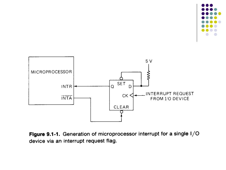
Interrupts Interrupts increase processor system efficiency by letting I/O device request CPU time only when that device needs immediate attention. An interrupt is a subroutine call initialized by external hardware.

4
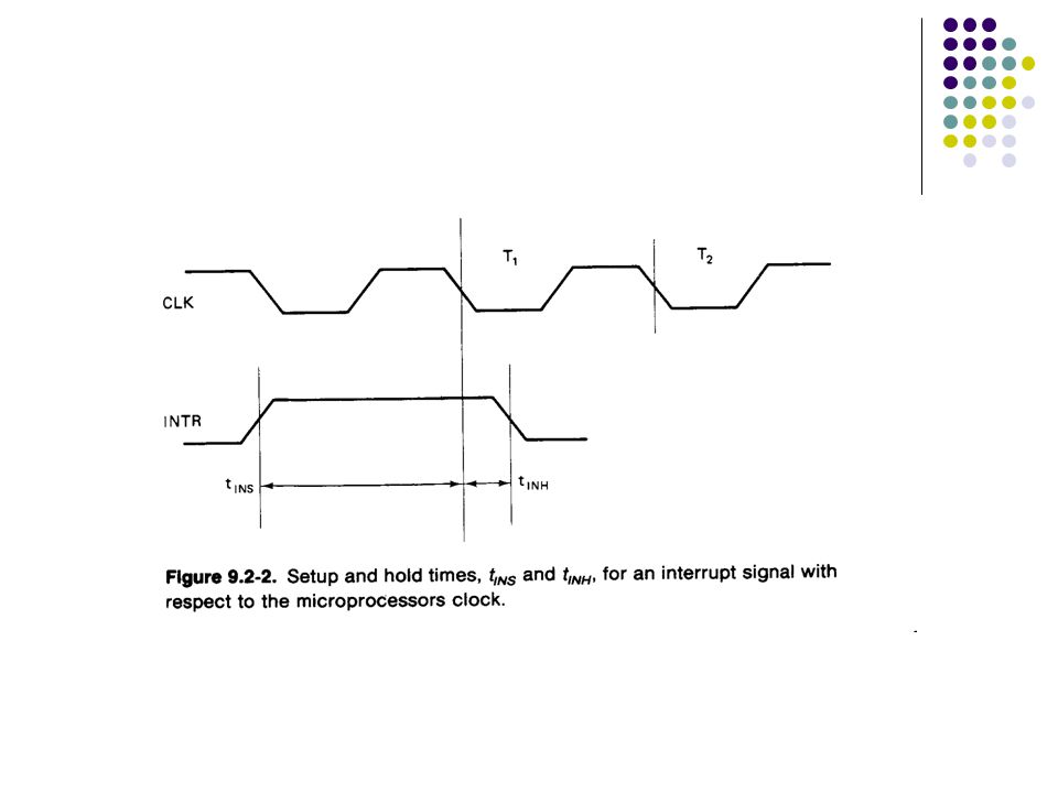
Interrupt Request The request is asynchronous it may occur at any point in a program’s execution.

5
Interrupt Input Types Nonmaskable interrupt input The MPU is interrupted when a logic signal is applied to this type of input. Maskable interrupt input The MPU is interrupted ONLY if that particular input is enabled. It is enabled or disabled under program control. If disabled, an interrupt signal is ignored by the MPU.

6
Maskable & Nonmaskable INT

7
Sequence of Actions

8
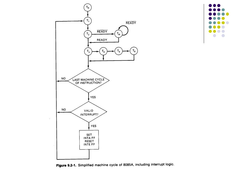
1. The processing of the current instruction is completed. 2. An interrupt machine cycle is executed during which the PC is saved and control is transferred to an appropriate memory location.

9
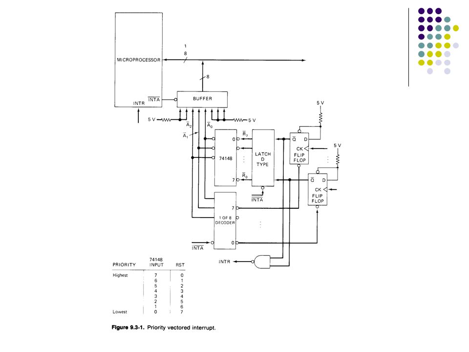
Sequence of Actions 3. The state of the MPU is saved. 4. If more than one I/O device is associated with the location transferred to, the highest priority device requesting an interrupt is identified.

10
Sequence of Actions 5. A subroutine is executed which services the interrupt I/O device. 6. The saved state of the microprocessor is restored. 7. Control is returned to the instruction that follows the interrupted instruction.

11
8085A Interrupt Structure There are 5 interrupt inputs: TRAP (nonmaskable) RST7.5 RST6.5 RST5.5 INTR
 RST7.5 RST6.5 RST5.5 INTR")
12
8085A Interrupt Structure When the 8085A is reset: Its internal interrupt enable flip-flop (INTE FF) is reset. This disables ALL the maskable interrupts. So, the MPU only responds to TRAP. Maskable interrupts must be enabled under program control. Let’s prove and find out which address the TRAP would go?

13
RST7.5, RST6.5, RST5.5 Two program steps are required to enable these interrupts: Setting the interrupt masks Enabling the interrupts SIM (set interrupt mask) is the instruction to mask each interrupt independently.
 is the instruction to mask each interrupt independently.")
14
8085A Interrupt Structure We can gather the status of maskable interrupt and interrupt enable/disable from the instruction RIM (Read Interrupt Mask)
")
15
INTR Although INTR is a maskable interrupt it does NOT need SIM to get enabled. Just instruction EI is enough.

16
Interrupt Inputs’ Sensitivity Level sensitive RST6.5 and RST 5.5 are high level sensitive The signal at these pins must be maintained until the interrupt is acknowledged External interrupt request flip-flops are required

17
Interrupt Inputs’ Sensitivity Edge sensitive RST7.5 (Rising edge sensitive) Only a pulse is required to set the interrupt request this request is remembered until the 8085A responds to the interrupt or until the request is reset by the SIM instruction or a /RESET IN signal. The interrupt request flip-flops for RST7.5 is internal to the microprocessor

18
Interrupt Inputs’ Sensitivity Both edge and level sensitive TRAP Must make a low-to-high transition and remain high to be acknowledged. After acknowledgement, it is NOT recognized again until it goes low, then high again and remains high. To avoid false triggering due to noise/logic glitches.

20
Remember This?

22
BUS IDLE (BI) Machine Cycle TRAP, RST5.5, RST6.5, and RST7.5 RST (internal) ((SP) – 1) (PCH) ((SP) – 2) (PCL) (SP) (SP) – 2 (PC) restart address
 Machine Cycle TRAP, RST5.5, RST6.5, and RST7.5 RST (internal) ((SP) – 1) (PCH) ((SP) – 2) (PCL) (SP) (SP) – 2 (PC) restart address")
23
INTERRUPT ACKNOWLEDGE (INA) Machine Cycle INTR ( 0 =< n =< 7 ) RST n ((SP) – 1) (PCH) ((SP) – 2) (PCL) (SP) (SP) – 2 (PC) 8*n External logic must generate interrupt vector as 11NNN111 at the data bus
 Machine Cycle INTR ( 0 =< n =< 7 ) RST n ((SP) – 1) (PCH) ((SP) – 2) (PCL) (SP) (SP) – 2 (PC) 8*n External logic must generate interrupt vector as 11NNN111 at the data bus")
25
Priority Interrupt Structures 8085A have an internally established, fixed, multilevel priority structure. From highest to lowest: TRAP Usually reserved to handle catastrophies such as power failures. RST7.5 RST6.5 RST5.5 INTR

Similar presentations


 is needed. Sources of interrupts: internal fault (e.g.. divide by.>")


