Download presentation
Presentation is loading. Please wait.

1
The Rare Isotope Science Project a.k.a. KoRIA IUPAP 2012 (Japan) 08. 17. 2012 Dong-O Jeon The Institute for Basic Science Dong-O Jeon The Institute for Basic Science

2
Brief History of IBS International Science Business Belt plan (2009.1) The Institute for Basic Science is the core facility of the ISBB plan Under the IBS, a heavy ion accelerator facility is built – The Rare Isotope Science Project Preliminary Design Study (2009.3 - 2010.2) Conceptual Design study (2010.3 - 2011.2) International Advisory Committee (2011.7) Institute for Basic Science(IBS) established (2011.11) Rare Isotope Science Project(RISP) launched (2011.12) Technical Advisory Committee (2012.5) Baseline Design Summary (2012.6) International Advisory Committee (2012.7)
 The Institute for Basic Science is the core facility of the ISBB plan Under the IBS, a heavy ion accelerator facility is built – The Rare Isotope Science Project Preliminary Design Study ( ) Conceptual Design study ( ) International Advisory Committee (2011.7) Institute for Basic Science(IBS) established ( ) Rare Isotope Science Project(RISP) launched ( ) Technical Advisory Committee (2012.5) Baseline Design Summary (2012.6) International Advisory Committee (2012.7)")
3
Organization of the Institute for Basic Science Auditor President Scientific Advisory Board Secretariats Office of Policy Planning Office of Research Services Office of Administrative Services Research Center (Headquarters) Research Center (Extramural) Accelerator Institute (Affiliated Institution) Board of Directors Research Center (Campus) Rare Isotope Science Project 4 50 research centersaffiliated research institutes IBS consists of 50 research centers, supporting organizations, and affiliated research institutes Each Research Center : ~50 staff, average annual budget ~ 9 M USD The number of staff: 3,000 (2017, including visiting scientists and students) Annual Budget: USD 610 million (2017, including operational cost for the Accelerator Institute)
 Research Center (Extramural) Accelerator Institute (Affiliated Institution) Board of Directors Research Center (Campus) Rare Isotope Science Project 4 50 research centersaffiliated research institutes IBS consists of 50 research centers, supporting organizations, and affiliated research institutes Each Research Center : ~50 staff, average annual budget ~ 9 M USD The number of staff: 3,000 (2017, including visiting scientists and students) Annual Budget: USD 610 million (2017, including operational cost for the Accelerator Institute)")
4
Location Daejeon

5
Bird Eye View of IBS

6
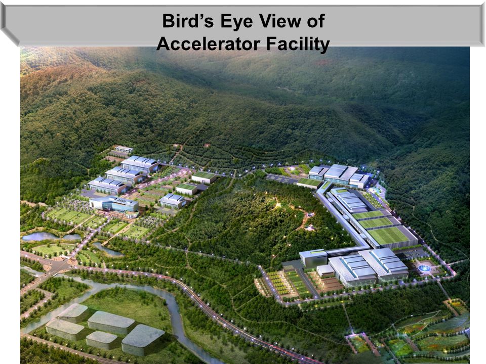
Bird’s Eye View of Accelerator Facility

8
Making Rare Isotope Beams IF(In-Flight Fragmentation) Stable Heavy ion beam thin target projectile fragmentation (high energy) ISOL(Isotope Separator On-Line) p thick target (eg. Uranium Carbide) target spallation or fission (low energy) RI Ions Reacceleration RI ion beam Stopping RI Beam Fast Beam Experiment Stopped Beam Experiment (Traps) Cyclotron Proton 70 MeV, 70 kW Driver LINAC Heavy ion e.g. U : 200MeV/u, 200 kW
 target spallation or fission (low energy) RI Ions Reacceleration RI ion beam Stopping RI Beam Fast Beam Experiment Stopped Beam Experiment (Traps) Cyclotron Proton 70 MeV, 70 kW Driver LINAC Heavy ion e.g. U : 200MeV/u, 200 kW.")
9
Accelerator System ECR-IS ( 10keV/u, 12 pμA) LEBT RFQ (300keV/u, 9.5 pμA) MEBT SCL1 (18.5 MeV/u, 9.5 pμA) SCL2 (200 MeV/u, 8.3 pμA for U +79 ) (600MeV, 660 μA for p) SCL1 (Post Acc.) ECR-IS RFQ MEBT CB HRMS RF Cooler ISOL Target Cyclotron (p, 70 MeV, 1mA) IF Target IF Separator Chg. Stripper Driver Linac Post Accelerator IF system ISOL system μSR, Medical Atomic Trap Gas Catcher Main Driver Superconducting Linac with 400 kW beam power Cyclotron 70 MeV 1 mA p beam as ISOL driver Post Accelerator to accelerate RI beams

10
Accelerator System AcceleratorDriver LinacPost Acc.Cyclotron ParticleprotonU +79 RI beamproton Beam energy600 MeV200 MeV/u18.5 MeV/u70 MeV Beam current660μA8.3 pμA-1 mA Power on target400 kW -70 kW Beam Parameters of Accelerator System

11
Driver Linac ECR-IS ( 10keV/u, 12 pμA) LEBT RFQ (300keV/u, 9.5 pμA) MEBT SCL1 (18.5 MeV/u, 9.5 pμA) SCL2 (200 MeV/u, 8.3 pμA for U +79 ) (600MeV, 660 μA for p) SCL1 (Post Acc.) ECR-IS RFQ MEBT CB HRMS RF Cooler ISOL Target Cyclotron (p, 70 MeV, 1mA) IF Target IF Separator Chg. Stripper Driver Linac Post Accelerator IF system ISOL system μSR, Medical Atomic Trap Gas Catcher Main Driver Linac with 400 kW beam power Accelerates from proton (600 MeV) to uranium (200 MeV/u) Designed for high intensity beams Send beam to the IF target or ISOL target Injector SCL2 SCL1
 to uranium (200 MeV/u) Designed for high intensity beams Send beam to the IF target or ISOL target Injector SCL2 SCL1.")
12
ECR Ion Source Consists of 28 GHz RF system and superconducting magnets for high current ion beam generation X-ray shielding required High temp oven under design Generating 12 p A (U beam) ECR-IS Ion BeamProton to Uranium beam Extraction Energy10 keV/u RF power10 kW Extraction Emittance0.1π mm-mrad Beam Current12 puA ( 238 U 33+, 238 U 34+ ) RF Frequence28GHz Superconducting Magnet
 ECR-IS Ion BeamProton to Uranium beam Extraction Energy10 keV/u RF power10 kW Extraction Emittance0.1π mm-mrad Beam Current12 puA ( 238 U 33+, 238 U 34+ ) RF Frequence28GHz Superconducting Magnet")
13
RFQ RFQ is To accelerate ion beams from 10 keV/u to 300 keV/u 4 m long, 81.25 MHz RFQ Input Energy10 keV/u Output Energy300 keV/u Input Emittance (rms)0.12π mm-rad Frequency81.25 MHz Input charge33, 34 (Uranium-238) Input current12 pμA Output current9.5 pμA
0.12π mm-rad Frequency81.25 MHz Input charge33, 34 (Uranium-238) Input current12 pμA Output current9.5 pμA")
14
RFQ x =0.12 mm-mrad, y =0.18 mm-mrad, z =8.2 MeV-deg @ exit of RFQ With LEBT bunchers (TRACK code) Accelerate ion beams 10 keV/u to 300 keV/u Assessing available options. Transmission : 80.5%

15
Driver SCL SCL is designed To accommodate the needs of various user groups To accelerate high intensity beams Nb Cavities operating at 2K Focusing by normal conducting quad doublets Optimized geometric beta of SC cavities (0.047, 0.12, 0.30, 0.53) Employs larger aperture to reduce beam loss (4cm and 5 cm aperture) Cryogenic load estimated 1.9 kW [Driver Linac 2K] + 0.35 kW [Post Acc] Cavity geometry optimized for E peak /E acc, B peak /E acc, R/Q, QR s
![Driver SCL SCL is designed To accommodate the needs of various user groups To accelerate high intensity beams Nb Cavities operating at 2K Focusing by normal conducting quad doublets Optimized geometric beta of SC cavities (0.047, 0.12, 0.30, 0.53) Employs larger aperture to reduce beam loss (4cm and 5 cm aperture) Cryogenic load estimated 1.9 kW [Driver Linac 2K] kW [Post Acc] Cavity geometry optimized for E peak /E acc, B peak /E acc, R/Q, QR s](http://images.slideplayer.com/13/3936675/slides/slide_15.jpg "Driver SCL SCL is designed To accommodate the needs of various user groups To accelerate high intensity beams Nb Cavities operating at 2K Focusing by normal conducting quad doublets Optimized geometric beta of SC cavities (0.047, 0.12, 0.30, 0.53) Employs larger aperture to reduce beam loss (4cm and 5 cm aperture) Cryogenic load estimated 1.9 kW [Driver Linac 2K] kW [Post Acc] Cavity geometry optimized for E peak /E acc, B peak /E acc, R/Q, QR s")
16
Cavity Geometric Beta Optimization 16 RISP: 0.047, 0.120, 0.30, 0.53 QWR HWR SSR1 SSR2 For U beam

17
Cavity Geometry Optimized ParametersUnitQWRHWRSSR 1SSR 2 gg -0.0470.120.300.53 Resonant frequencyMHz81.25162.5325 No of cavities-2413888136 Aperture diametermm40 50 QR s Ohm374786108 R/QOhm480319242304 V acc MV1.021.072.043.53 E peak MV/m30 B peak mT48415457 E peak /E acc 5.086.24.064.15 B peak /E acc 9.168.47.078.6 Q calc /10 9 -3.64.68.110 Operating temperatureK2222 P0P0 W1.31.54.77.9 P beam / emA (proton)W85492514402770 P beam / emA (Uranium)W113134524926 Average charge state (U)-33.5 79
W P beam / emA (Uranium)W Average charge state (U)")
18
SCL Layout 18 NC quadrupole Previous Driver SCL Design with SC solenoids Driver SCL with NC doublets SC cavityQWR beam box HWR Linac base frequency = 81.25 MHz Design to accelerate high intensity ion beams Flexile operation to meet the needs of various user groups

19
SCL Layout NC quadrupole lattice option has the following merits: 1.Accurate alignment < 150 mm of NC quadrupoles is straightforward. 2.Beam quality control is straightforward and design is more adequate for high power beam operation. 3.Advantages in beam diagnostics and collimation through beam boxes. 4.The linac cost seems to be in error range compared with the SC solenoid option. ( removal of costly SC solenoids) 5.Preliminary cryo-load comparison suggests that overall cryo-load difference is small compared with the dynamic load.
 5.Preliminary cryo-load comparison suggests that overall cryo-load difference is small compared with the dynamic load..")
20
SCL Layout collimatorquadrupolecryomodule Present SCL layout provides good beam diagnostics configuration for machine tuning. Necessary beam diagnostics can be installed at beam boxes. Also provides good beam loss collimation configuration, improving beam quality for users, reducing beam loss. Beam loss Beam beam box

21
SCL Layout [1 QWR + 1 QD] x 24 [3 HWR + 1 QD] x 14 [6 HWR + 1 QD] x 16 [4 SSR + 1 QD] x 22 SCL Cavity structure Frequencyβgβg Number of cavities Output energy SCL1 QWR81.25 MHz0.047242.5 MeV/u (U +33 ) HWR162.5 MHz0.1213818.6 MeV/u (U +33 ) SCL2 SSR325 MHz0.308871 MeV/u (U +79 ) SSR325 MHz0.53136200 MeV/u (U +79 ) [8 SSR + 1 QD] x 17 beam box example (courtesy of SPIRAL2) SCL1 SCL2
![SCL Layout [1 QWR + 1 QD] x 24 [3 HWR + 1 QD] x 14 [6 HWR + 1 QD] x 16 [4 SSR + 1 QD] x 22 SCL Cavity structure Frequencyβgβg Number of cavities Output energy SCL1 QWR81.25 MHz MeV/u (U +33 ) HWR162.5 MHz MeV/u (U +33 ) SCL2 SSR325 MHz MeV/u (U +79 ) SSR325 MHz MeV/u (U +79 ) [8 SSR + 1 QD] x 17 beam box example (courtesy of SPIRAL2) SCL1 SCL2](http://images.slideplayer.com/13/3936675/slides/slide_21.jpg "SCL Layout [1 QWR + 1 QD] x 24 [3 HWR + 1 QD] x 14 [6 HWR + 1 QD] x 16 [4 SSR + 1 QD] x 22 SCL Cavity structure Frequencyβgβg Number of cavities Output energy SCL1 QWR81.25 MHz MeV/u (U +33 ) HWR162.5 MHz MeV/u (U +33 ) SCL2 SSR325 MHz MeV/u (U +79 ) SSR325 MHz MeV/u (U +79 ) [8 SSR + 1 QD] x 17 beam box example (courtesy of SPIRAL2) SCL1 SCL2")
22
SCL machine tolerance (Driver SCL, Post SCL) Machine imperfections for actual accelerator Parameters SCRF Cavity Warm Quadrupole SC Solenoid Distribution Displacement (mm)±1±0.15±0.5Uniform Rotation (mrad)-±5-Uniform Phase (deg)±1--3σ Gaussian Amplitude (%)±1--3σ Gaussian Preliminary study is done. Further studies on machine tolerances will be done.

23
SCL machine tolerance The shade region represents the bounds of envelope, centroid a nd emittance due to misalignment and field errors. The aperture of quadrupole and solenoid is 4 cm. Max. envelopeCentroid Emittance baseline solenoid 10% increase 130% increase 76% increase 350% increase

24
Cyclotron ECR-IS ( 10keV/u, 12 pμA) LEBT RFQ (300keV/u, 9.5 pμA) MEBT SCL1 (18.5 MeV/u, 9.5 pμA) SCL2 (200 MeV/u, 8.3 pμA for U +79 ) (600MeV, 660 μA for p) SCL1 (Post Acc.) ECR-IS RFQ MEBT CB HRMS RF Cooler ISOL Target Cyclotron (p, 70 MeV, 1mA) IF Target IF Separator Chg. Stripper Driver Linac Post Accelerator IF system ISOL system μSR, Medical Atomic Trap Gas Catcher Cyclotron Cyclotron – 70 MeV, 1 mA, proton beam Supports CW and pulsed beam Pulsed beam by fast chopping system Driver for the ISOL target Will be procured through bidding

25
Post-Accelerator System ECR-IS ( 10keV/u, 12 pμA) LEBT RFQ (300keV/u, 9.5 pμA) MEBT SCL1 (18.5 MeV/u, 9.5 pμA) SCL2 (200 MeV/u, 8.3 pμA for U +79 ) (600MeV, 660 μA for p) SCL1 (Post Acc.) ECR-IS RFQ MEBT CB HRMS RF Cooler ISOL Target Cyclotron (p, 70 MeV, 1mA) IF Target IF Separator CS Driver Linac Post Accelerator IF system ISOL system μSR, Medical Atomic Trap Gas Catcher Accelerates RI beams from the ISOL system up to 18.5 MeV/u and RI beam can be injected to SCL2 to higher energy Consists of charge breeder, RFQ, MEBT, superconducting linac etc. High beam quality required Adopts the same SCL layout

26
Design of IF Separator W. Wan, J. Kim, Cyclotron Conf. 2010 Pre-separator: S-shape Main separator: C-shape Max. magnetic rigidity= 8 T m

27
Beam Optics of Pre-Separator p/p= 1.5% Aberrations up to 7 th order Horizontal Vertical Beam dump Wedge Shielding Calculated with TURTLE = 4 mm mrad p/p = 5 %

28
Schedule SAR (Safety Analysis Report) Review is a critical path to accelerator system installation and commissioning. Rather optimistic schedule for SAR Review process is assumed. Accelerator tunnel construction begins Feb/01/2016. Installation of accelerators will begin Jul/01/2016.

29
Schedule

30
Very tight installation and commissioning schedule to meet the 2017 completion

31
Organization Chart SCL Team Kim, Hyung Jin (leader) Jung, Hoe Chun Lee, Jung Han Choi, Chul Jin Joo, Jong Dae IF ∙ RF Team Kim, Jong Won (leader) Han, Jae Eun Kim, Mi Jung Kim, Do Gyun Kim, Myeong Jin Song, Jeong Seog Kim, Seong Jun Injector ∙ Beam Phy Team Hong, In Seok (leader) Kim, Byoung Chul Choi, Bong Hyuk Seo, Chang Seok Kim, Hye Jin Jang, Si Won Hwang, Ji Gwang Bang, Jung Bae Accelerator Sys. Division Jeon, Dong-O Rare Isotope Science Project Kim, Sun Kee Experimental Sys. Division Kim, Yong Kyun Recruiting on-going

32
Man-power Plan 20122013201420152016Total Young scientists / engineers 20 1210870 Budget (\100M) 10 65435 Recruiting Plan for young scientists and engineers Project-wise Man-power Plan 2011201220132014201520162017 Regular (Termed) 1 (0) 33 (39) 50 (50) 116 (50) 130 (50) 140 (50) 150 (50)
 Recruiting Plan for young scientists and engineers Project-wise Man-power Plan Regular (Termed) 1 (0) 33 (39) 50 (50) 116 (50) 130 (50) 140 (50) 150 (50)")
33
Summary Previous conceptual design was reviewed / assessed and design changes are made (reflected in Baseline Design Summary). The RISP is phasing into technical design stage. Schedule and Cost are being evaluated. Having developed man-power plan to support the schedule. We are getting ready for the construction of the SRF Test Facility. International Collaboration is an important part for the success of the project.

34
Thanks for Your Attention!

Similar presentations


 Steve Holmes Fermilab Proton Accelerators for Science and Innovation: Second Annual Meeting Rutherford Appleton Laboratory.>")

 On behalf of Conceptual Design Project Team S.>")


>")
 17/04/07 Kota Okabe (Fukui Univ.) for FFAG-DDS group.>")


 On behalf of Conceptual Design Project Team S.>")


 Institute for Basic Science (IBS ) In collaboration with: Ik Jae Shin, RISP,>")
