Download presentation
Presentation is loading. Please wait.

1
Emission control technology for marine applications

3
Diesel engines present in marine applications NameLow speedMedium SpeedHigh Speed Displacement (l/cyl)200 - 200016-1205 - 160,8 - 3< 0,8 Power range (kW)4000 – 100000800 - 40000 kWUp to 10000 kWUp to 800 kWUp to 300 kW Applications Marine Powergen Marine Rail Powergen Marine Rail Powergen Industrial Agriculture Mining Heavy duty Marine Rail Powergen Industrial Agriculture Mining Passenger car Light duty Industrial Agriculture Combustion type2-stroke & 4 stroke 4 stroke Rotation speed (rpm)70-300350 - 850600 - 2200600 - 3000>3000 DEC SCOPE Trend in repowering
 ,8 - 3< 0,8 Power range (kW)4000 – kWUp to kWUp to 800 kWUp to 300 kW Applications Marine Powergen Marine Rail Powergen Marine Rail Powergen Industrial Agriculture Mining Heavy duty Marine Rail Powergen Industrial Agriculture Mining Passenger car Light duty Industrial Agriculture Combustion type2-stroke & 4 stroke 4 stroke Rotation speed (rpm) >3000 DEC SCOPE Trend in repowering")
4
4 DPF Diesel particulate filter / Captures and oxidizes PM Frequently used on passenger car E5/E6 Frequently used on trucks EPA ‘07 Implemented for many trucks EUR VI Good potential for rail applications Good potential for inland vessel / local legislation SCR Selective catalytic reduction / Reduces NO X by means of a reagent Frequently used on trucks EUR IV,V,VI Best potential for inland vessel emission reduction Best potential for MARPOL TIER III After treatment solutions for diesel engines Possible with high sulphur fuel Fuel optimised engine => LOW CO 2 Possible with fuel below 250 - 350 PPM sulphur

5
Aftertreatment technology for inland vessels

6
Inland vessels have access to good quality fuel Facts Inland vessels use mainly medium and high speed diesel engines A high proportion of inland vessels have engine load profiles allowing the use of high efficient aftertreatment technology

7
DPF Regeneration during engine operation Active system Fuel exhaust injection Electrical Burner Combination Passive system NO2 Combination with FBC Offline systems Electrical Paper cartridge DPF solutions for marine diesel engines Best combination for inland vessels

8
SCR Dosing Airless Airassisted Catalyst sulphur resistance Vanadium type catalyst sulphur Sensitive catalysts FE-ZE / CU-ZE Require N02 content Reagent AD-BLUE UREA 40% solution AMMONIA SCR solutions

9
SCR Dosing Airless Airassisted Catalyst sulphur resistance Vanadium type catalyst sulphur Sensitive catalysts FE-ZE / CU-ZE Require N02 content Reagent Urea 32,5 / AUS 32 / DEF / ADblue UREA 40% solution AMMONIA SCR solutions inland vessels

10
10 Combined aftertreatment systems for inland vessel applications

11
Option 1 : DPF => SCR Engine C/DPF DOC / DEC SCR ASC AdBlue injecton Hydro Cat. Temp 1Temp 3Temp 4Temp 2Temp 5Press 1Press / Ref 2 NO X Diesel injecton Mixer Engine AdBlue injecton C/DPF DOC / DEC SCR Hydro Cat. Temp 1Temp 3Temp 4Temp 2Temp 5Press 1NO X DOC Diesel injecton Mixer Option 2 : SCR => DPF Not suitable for marine

12
Option 3 : SCRF Engine AdBlue injecton SCRF Temp 1Temp 3Temp 4Press 1NO X DOC/DEC Diesel injecton Temp 2 Mixer ASC Engine C/DPF DOC / DEC SCR ASC AdBlue injecton Temp 1Temp 3Temp 4Temp 2Temp 5Press 1Press / Ref 2 NO X Diesel injecton Mixer

13
Option 1 DPF => SCR Option 2 SCR => DPF Option 3 SCRF DPF regeneration via NO 2 / fuel penalty for regeneration++-+ N° of substrates* *(without hydrolysing catalyst and with end-zone coating for ASC when applicable) 342 Total substrate volume / compactness of the systemMedium volumeHighest volumeLowest volume Passive & active heat management / fuel penalty High thermal inertia Low thermal inertia Complexity of the temperature managementHigh Medium N° of cans N° of temperature sensors 3 cans minimum 4 (optional 5) 4 cans minimum 4 (optional 5) 2 cans minimum 3 (optional 4) Integration / geometrical freedom Installation -+++ Marine specific Low SV – Low Pressure drop requirement--+ System layout combined DPF / SCR
 342 Total substrate volume / compactness of the systemMedium volumeHighest volumeLowest volume Passive & active heat management / fuel penalty High thermal inertia Low thermal inertia Complexity of the temperature managementHigh Medium N° of cans N° of temperature sensors 3 cans minimum 4 (optional 5) 4 cans minimum 4 (optional 5) 2 cans minimum 3 (optional 4) Integration / geometrical freedom Installation -+++ Marine specific Low SV – Low Pressure drop requirement--+ System layout combined DPF / SCR")
14
14 Some test results with SCRF

15
Engine & system information 15 KW Engine= 88 Natural aspirated 6 cyl in Line Engine Disp.= 4200 cc Mullite Aerify substrate SCRF 5,8 dm³ Metal DOC volume 2,8 dm³ Engine & system information

16
16 Results sorted by Qex (exhaust gas volume flow in dm³/sec) Data sorted by exhaust gas volume flow
 Data sorted by exhaust gas volume flow")
17
Results sorted by Qex (exhaust gas volume flow in dm³/sec) NOX PPM on right axis =>
 NOX PPM on right axis =>")
18
NO X engine out5,52g/kWh ModeNO X conversionTemp 3Urea consumption NO X Tailpipe0,38g/kWh NO X conversion (average)93.1% Avg temp before SCRF353degC %°Cµl/s Adblue consumption0,204l1 87,0 2107 Conclusions: SCRF technology is capable of NOx reductions > 90%. 2 85,7 46094 3 93,6 335105 4 98,1 385125 5 98,6 31092 6 99,5 365113 7 95,0 25042 8 92,0 480107 9 84,9 27555 10 86,3 510123 11 87,3 29066 12 97,3 390142 13 99,4 330115 ESC Test run n° 5 ESC

19
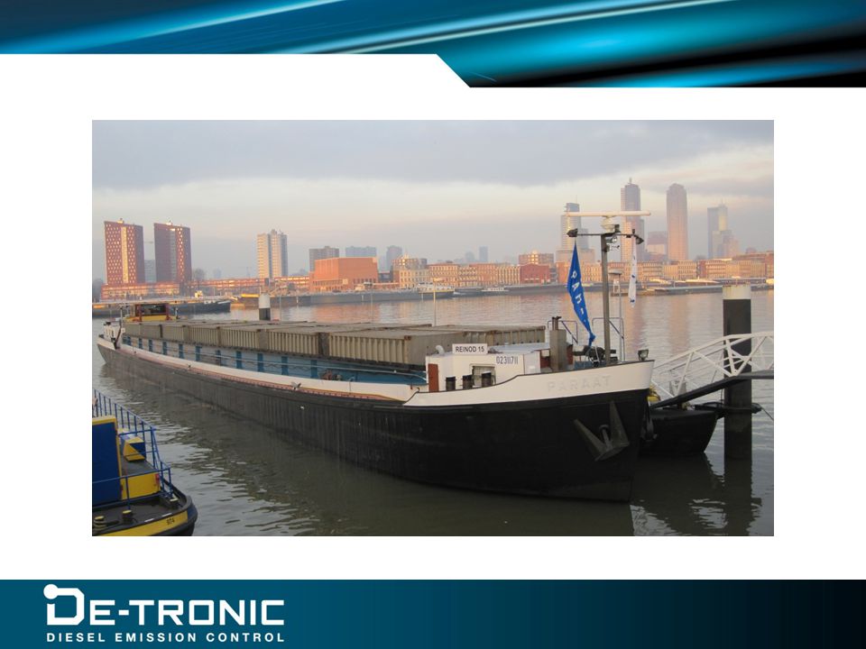
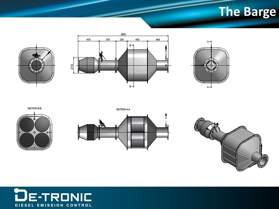
Validation of SCRF on two ships Barge This is considered as a normal application Engine: Scania V8 16 liter 450 kW Police Patrol ship Considered as a worst case scenario Engine : 2 x MTU V2000-01 600 kW

20
Data Analysis Barge

21
The Barge

23
Data Analysis Police Patrol Ship

26
The patrol ship

29
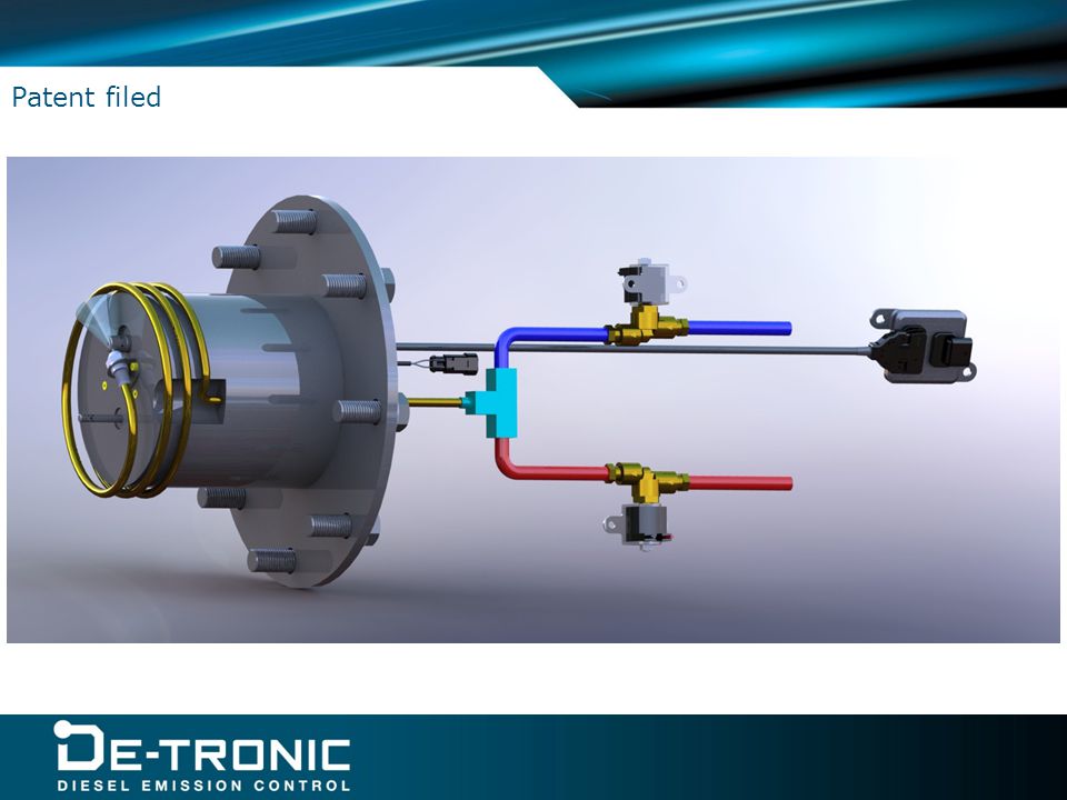
29 A new technology for NOx measurement on ships using low quality fuels Patent filed

30
Urea dosers Sensor integration in the exhaust Patent filed

32
DE-Tronic A Modular Electronic Platform for Diesel Emission Control Devices Key Product DE-TRONIC is an Electronic Control Unit (ECU) developed as a link between the engine and the diesel emission after treatment systems.
 developed as a link between the engine and the diesel emission after treatment systems.")
33
Functions DPF Monitoring DPF Active regeneration Diesel Post Injection Burner Control* Electrical heaters SCR control Urea dosing Ammonia dosing Tank / line temperature management FBC Dosing Data Logging OBD Telemetry*EGR control* PC interfaceGraphic data analysis

34
Thank you for your attention

Similar presentations