Download presentation
Presentation is loading. Please wait.

1
4/13/2017 Unit I

2
Combustion Stoichiometry Air/Fuel Ratio Equivalence Ratio
4/13/2017 Combustion Basics Fuel Combustion Stoichiometry Air/Fuel Ratio Equivalence Ratio Air Pollutants from Combustion

3
Fuel Gaseous Fuels Liquid Fuels Solid Fuels Natural gas Refinery gas
4/13/2017 Fuel Gaseous Fuels Natural gas Refinery gas Liquid Fuels Kerosene Gasoline, diesel Alcohol (Ethanol) Oil Solid Fuels Coal (Anthracite, bituminous, subbituminous, lignite) Wood
 Oil. Solid Fuels. Coal (Anthracite, bituminous, subbituminous, lignite) Wood.")
4
Fuel Properties of Selected Fuels
4/13/2017 Fuel Properties of Selected Fuels CH C2H C3H8 Other HCs H2S Heating Value (wt%) (106 J/m3) Natural gas (No.1) Natural gas (No.2) (Ultimate analysis) C H N O S Heating value (wt%) (106 J kg-1) Gasoline (No.2) (Approximate analysis) Carbon Volatile matter Moisture Ash Heating value (%) (%) (%) (%) (106 J kg-1) Anthracite (PA) Bituminous (PA) Subbituminous (CO) Lignite (ND) Which one has a higher energy density per mass? Do they burn in the same way? Data from Flagan and Seinfeld, Fundamentals of Air Pollution Engineering, 1988, Prentice-Hall.
 (106 J/m3) Natural gas (No.1) Natural gas (No.2) (Ultimate analysis) C H N O S Heating value. (wt%) (106 J kg-1) Gasoline (No.2) (Approximate analysis) Carbon Volatile matter Moisture Ash Heating value. (%) (%) (%) (%) (106 J kg-1) Anthracite (PA) Bituminous (PA) Subbituminous (CO) Lignite (ND) Which one has a higher energy density per mass Do they burn in the same way Data from Flagan and Seinfeld, Fundamentals of Air Pollution Engineering, 1988, Prentice-Hall.")
5
Combustion Stoichiometry
4/13/2017 Combustion Stoichiometry Combustion in Oxygen Can you balance the above equation? Write the reactions for combustion of methane and benzene in oxygen, respectively. Answer

6
Combustion Stoichiometry
4/13/2017 Combustion Stoichiometry Combustion in Air (O2 = 21%, N2 = 79%) Can you balance the above equation? Write the reactions for combustion of methane and benzene in air, respectively. Answer 1. What if the fuel contains O, S, Cl or other elements? 2 Is it better to use O2 or air?
 Can you balance the above equation Write the reactions for combustion of methane and benzene in air, respectively. Answer. 1. What if the fuel contains O, S, Cl or other elements 2 Is it better to use O2 or air")
7
Aerosol & Particulate Research Laboratory
4/13/2017 Air-Fuel Ratio Air-Fuel (AF) ratio AF = m Air / m Fuel Where: m air = mass of air in the feed mixture m fuel = mass of fuel in the feed mixture Fuel-Air ratio: FA = m Fuel /m Air = 1/AF Air-Fuel molal ratio AFmole = nAir / nFuel Where: nair = moles of air in the feed mixture nfuel = moles of fuel in the feed mixture What is the Air-Fuel ratio for stoichiometric combustion of methane and benzene, respectively? 4/13/2017 Aerosol & Particulate Research Laboratory
 ratio. AF = m Air / m Fuel. Where: m air = mass of air in the feed mixture. m fuel = mass of fuel in the feed mixture. Fuel-Air ratio: FA = m Fuel /m Air = 1/AF. Air-Fuel molal ratio. AFmole = nAir / nFuel. Where: nair = moles of air in the feed mixture. nfuel = moles of fuel in the feed mixture. What is the Air-Fuel ratio for stoichiometric combustion of methane and benzene, respectively 4/13/2017. Aerosol & Particulate Research Laboratory.")
8
Aerosol & Particulate Research Laboratory
4/13/2017 Air-Fuel Ratio Rich mixture - more fuel than necessary (AF) mixture < (AF)stoich Lean mixture - more air than necessary (AF) mixture > (AF)stoich Most combustion systems operate under lean conditions. Why is this advantageous? Consider the combustion of methanol in an engine. If the Air-Fuel ratio of the actual mixture is 20, is the engine operating under rich or lean conditions? 4/13/2017 Aerosol & Particulate Research Laboratory
 mixture < (AF)stoich. Lean mixture. - more air than necessary. (AF) mixture > (AF)stoich. Most combustion systems operate under lean conditions. Why is this advantageous Consider the combustion of methanol in an engine. If the Air-Fuel ratio of the actual mixture is 20, is the engine operating under rich or lean conditions 4/13/2017. Aerosol & Particulate Research Laboratory.")
9
Aerosol & Particulate Research Laboratory
4/13/2017 Equivalence Ratio Equivalence ratio: shows the deviation of an actual mixture from stoichiometric conditions. The combustion of methane has an equivalence ratio Φ=0.8 in a certain condition. What is the percent of excess air (EA) used in the combustion? How does temperature change as Φ increases? 4/13/2017 Aerosol & Particulate Research Laboratory
 used in the combustion How does temperature change as Φ increases 4/13/2017. Aerosol & Particulate Research Laboratory.")
10
Formation of NOx and CO in Combustion
4/13/2017 Formation of NOx and CO in Combustion Thermal NOx Oxidation of atmospheric N2 at high temperatures Formation of thermal NOx is favorable at higher temperature Fuel NOx Oxidation of nitrogen compounds contained in the fuel Formation of CO Incomplete Combustion Dissociation of CO2 at high temperature 4/13/2017 Aerosol & Particulate Research Laboratory

11
Air Pollutants from Combustion
4/13/2017 Air Pollutants from Combustion Source: Seinfeld, J. Atmospheric Chemistry and Physics of Air Pollution. How do you explain the trends of the exhaust HCs, CO, and NOx as a function of air-fuel ratio? How do you minimize NOx and CO emission?

12
Combustion Stoichiometry Air/Fuel Ratio Equivalence Ratio
4/13/2017 Quick Reflections Fuel Combustion Stoichiometry Air/Fuel Ratio Equivalence Ratio Air Pollutants from Combustion

13
Engine Fuel System (SI Petrol)
Fuel Tank – normally positioned in the rear boot area, either under the floor pan for estate cars or over the rear axle for saloons, the latter being a safer position. Should the engine be mounted in the rear, the fuel tank is normally positioned in the front boot area, either over the bulkhead or flat across the boot floor pan , the latter providing more boot space, but is more exposed to danger in a head on crash. The fuel tank made be made from pressed steel and coated inside to prevent corrosion, or a synthetic rubber compound or flame resistant plastic. Inside the fuel tank is normally located the fuel gauge sender unit and electrically driven fuel pump with a primary filter in a combined module. Internal fuel tank baffles are used to prevent fuel surge. The fuel tank is pressurised to about 2 psi to prevent fuel vaporization and pollution. The fuel tank is vented through its own venting system and the engine managements emission control systems again to control pollution. Fuel pipes – These can be made from steel or plastic and are secured by clips at several points along the underside of the vehicle. To allow for engine movement and vibration, rubber hoses connect the pipes to the engine. Later fuel pipes use special connectors which require special tools to disconnect the pipes.

14
Engine Fuel System (SI Petrol)
Fuel Filters – to prevent dirt and fluff entering the fuel pump a filter is fitted on the suction side of the pump. On the pressure side of the pump a secondary filter is used, this is a much finer filter in that it prevents very small particles of dirt reaching the carburettor or fuel injection equipment. It should be renewed at the correct service interval as recommended by the manufacturer. When the filter is replaced, it must be fitted in the direction of fuel flow. Air Filters – air cleaners and silencers are fitted to all modern vehicles. Its most important function is to prevent dust and abrasive particles from entering the engine and causing rapid wear. Air filters are designed to give sufficient filtered air, to obtain maximum engine power. The air filter must be changed at the manufactures recommended service interval. The air filter/cleaner also acts as a flame trap and silencer for the air intake system. Fuel Pump – this supplies fuel under high pressure to the fuel injection system, or under low pressure to a carburettor. Carburettor – this is a device which atomizes the fuel and mixes it which the correct amount of air, this device has now been superseded by modern electronic fuel injection.

15
Petrol Petrol

16
Float chamber (function) – to set and maintain the fuel level within the carburettor, and to control the supply fuel to the carburettor venturi. Operation – when air passes through the venturi due to the engines induction strokes, it creates a depression (suction), around the fuel spray outlet. Atmospheric pressure is acting on the fuel in the float chamber, the difference in theses pressures causes the fuel to flow from the float chamber, through the jet and into the stream. This causes the petrol to mix with the air rushing in to form a combustible mixture. The required air fuel ratio can be obtained by using a jet size which allows the correct amount of fuel to flow for the amount of air passing through the Defects of the simple carburettor. As engine speed increases, air pressure and density decreases i.e. the air gets thinner, however the quantity of fuel increases i.e. greater pressure exerted on the fuel, this causes the air/fuel mixture to get progressively richer (to much fuel). As the engine speed decreases, the air/fuel mixture becomes progressively weaker. Some form of compensation is therefore required so that the correct amount of air and fuel is supplied to the engine under all operating conditions.
, around the fuel spray outlet. Atmospheric pressure is acting on the fuel in the float chamber, the difference in theses pressures causes the fuel to flow from the float chamber, through the jet and into the stream. This causes the petrol to mix with the air rushing in to form a combustible mixture. The required air fuel ratio can be obtained by using a jet size which allows the correct amount of fuel to flow for the amount of air passing through the. Defects of the simple carburettor. As engine speed increases, air pressure and density decreases i.e. the air gets thinner, however the quantity of fuel increases i.e. greater pressure exerted on the fuel, this causes the air/fuel mixture to get progressively richer (to much fuel). As the engine speed decreases, the air/fuel mixture becomes progressively weaker. Some form of compensation is therefore required so that the correct amount of air and fuel is supplied to the engine under all operating conditions.")
17
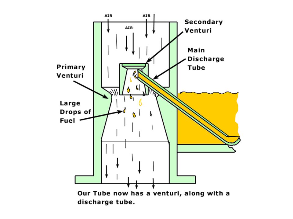
The Simple Carburettor Petrol Operation of the Venturi
The Float Chamber Petrol Operation of the Venturi Choke Valve closed The Throttle Valve controls the amount of air fuel mixture entering the engine and therefore engine power The Choke Valve is used to provide a rich air/fuel ratio for cold starting

22
Air Fuel Ratio Fuel mixture strengths – petrol will not burn unless it is mixed with air, to obtain the best possible combustion of the fuel, which should result in good engine power and fuel consumption and low emissions (pollution), the air fuel ratio must be chemically correct i.e. the right amount of air and fuel must be mixed together to give an air fuel ratio of 14.7 to 1 by mass. This is referred to as the shoitcmetreic air fuel ratio, this ratio can also be describe by the term Lambda. Lamba is the Greek word meaning ‘air’. When their is more air present than fuel in the air fuel mixture, it is said to be ‘weak’ or ‘lean’ i.e. not enough fuel e.g. a ratio of 25 to 1, this results in a Lambda reading of more than 1.When their is not enough air present, the mixture is referred to as ‘rich’ e.g. a air fuel ratio of 8 to 1, in this case Lambda equals less than 1. Weak/lean air/fuel mixtures – can result in low fuel consumption, low emissions (pollution), however, weak air fuel mixtures can also result in poor engine performance (lack of power) and high engine temperatures ( because the fuel burns more slowly) Rich air/ fuel mixtures – can result in greater engine power, however this also results in poorer fuel consumption and greatly increased emissions (pollution)
, the air fuel ratio must be chemically correct i.e. the right amount of air and fuel must be mixed together to give an air fuel ratio of 14.7 to 1 by mass. This is referred to as the shoitcmetreic air fuel ratio, this ratio can also be describe by the term Lambda. Lamba is the Greek word meaning ‘air’. When their is more air present than fuel in the air fuel mixture, it is said to be ‘weak’ or ‘lean’ i.e. not enough fuel e.g. a ratio of 25 to 1, this results in a Lambda reading of more than 1.When their is not enough air present, the mixture is referred to as ‘rich’ e.g. a air fuel ratio of 8 to 1, in this case Lambda equals less than 1. Weak/lean air/fuel mixtures – can result in low fuel consumption, low emissions (pollution), however, weak air fuel mixtures can also result in poor engine performance (lack of power) and high engine temperatures ( because the fuel burns more slowly) Rich air/ fuel mixtures – can result in greater engine power, however this also results in poorer fuel consumption and greatly increased emissions (pollution)")
23
Engine S I Fuel System ECU – Electronic control unit. This contains a computer which takes information from sensors and controls the amount of fuel injected by operating the injectors for just the right amount of time. Air flow/mass meter – A sensor used to tell the ECU how much air is being drawn into the engine. MAP sensor – Manifold absolute pressure sensor. This senses the pressure in the engines inlet manifold, this gives an indication of the load the engine is working under. Speed/crankshaft sensor – This tells the ECU has fast the engine is rotating and sometimes the position of the crankshaft. Temperature sensor – Coolant temperature is used determine if more fuel is needed when the engine is cold or warming up. Lambda sensor – A sensor located in the exhaust system which tells the ECU the amount of oxygen in the exhaust gases, form this the ECU can determine if the air/fuel ratio is correct. Fuel pump – A pump, normally located in the fuel tank, which supplies fuel under pressure to the fuel injectors.

24
Engine S I Fuel System Fuel filter – keeps the fuel very clean to prevent the injectors becoming damaged or blocked. Fuel rail – A common connection to multi point injectors, acts a reservoir of fuel (small tank of fuel). Injector – A electrical device which contains a winding or solenoid. When turned on by the ECU, the injector opens and fuel is sprayed into the inlet manifold, or into the combustion chamber itself. Idle actuator – A valve controlled by the ECU which controls the idle speed of the engine. ECU – Electronic Unit. This contains a computer which takes information from sensors and controls the amount of fuel injected by operating the injectors for just the right amount of time. The ECU also controls the operation of the ignition and the other engine rated systems.
. Injector – A electrical device which contains a winding or solenoid. When turned on by the ECU, the injector opens and fuel is sprayed into the inlet manifold, or into the combustion chamber itself. Idle actuator – A valve controlled by the ECU which controls the idle speed of the engine. ECU – Electronic Unit. This contains a computer which takes information from sensors and controls the amount of fuel injected by operating the injectors for just the right amount of time. The ECU also controls the operation of the ignition and the other engine rated systems.")
25
Typical Fuel System 1. Fuel Supply System
Components that supply clean fuel to the fuel metering system (fuel pump, fuel pipes, fuel filters). 2. Air Supply System Components that supply controlled clean air to the engine (air filter, ducting, valves). 3. Fuel Metering System Components that meter the correct amount of fuel (and air) entering the engine (injectors, pressure regulator, throttle valve). The exact components used will vary with fuel system type and design. 25 of 14
. 2. Air Supply System. Components that supply controlled clean air to the engine (air filter, ducting, valves). 3. Fuel Metering System. Components that meter the correct amount of fuel (and air) entering the engine (injectors, pressure regulator, throttle valve). The exact components used will vary with fuel system type and design. 25 of 14.")
26
Introduction to Electronic Petrol Throttle/Single Point Fuel Injection Systems
The Carburettor has now been replaced with petrol injection systems. These systems supply the engine with a highly atomized mixture of air and fuel in the correct air/fuel ratio. This has the following advantages over the carburettor systems Lower exhaust emissions (pollution) Better fuel consumption Smoother engine operation and greater power Automatic adjustment of the air/fuel ratio to keep the vehicles emissions (pollution) to a minimum. 26 of 14
 Better fuel consumption. Smoother engine operation and greater power. Automatic adjustment of the air/fuel ratio to keep the vehicles emissions (pollution) to a minimum. 26 of 14.")
27
Throttle Body/Single Point S.I. Fuel Injection
Air drawn in by the engine Throttle Body/Single Point S.I. Fuel Injection Throttle Body Fuel Supply Fuel Injector (one off) Throttle Valve Inlet Manifold The Engine
 Throttle Valve. Inlet Manifold. The Engine.")
28
Single Point Electronic Fuel Injection (EFI) Systems
EFI systems are classified by using the point of injection. ECU Fuel in Inlet manifold Air in TB injector Single Point (Throttle Body) Fuel Injection A fuel injector (may be 2) is located in a throttle body assembly that sits on top of the inlet manifold. Fuel is sprayed into the inlet manifold from above the throttle valve, mixing with incoming air. Fuel quantity, how much feul is injected is controlled by an ECU. 28 of 14
 Fuel Injection. A fuel injector (may be 2) is located in a throttle body assembly that sits on top of the inlet manifold. Fuel is sprayed into the inlet manifold from above the throttle valve, mixing with incoming air. Fuel quantity, how much feul is injected is controlled by an ECU. 28 of 14.")
29
Electronic Fuel Injector Operation
An injector sprays fuel into the inlet manifold by use of a solenoid coil. When the coil is switch on by the ECU, it pulls the armature/needle valve away from the nozzle, allowing pressurized fuel into the engine. When the coil is not switched on, the spring pushes the armature/needle against the nozzle, no fuel is injected into the inlet manifold Injectors are more precise and efficient than carburettors. Electrical connector Solenoid coil Needle valve Fuel in Nozzle/jet Armature Spring Fuel filter

30
Single Point Injection
Sensor Inputs Single Point Injection Outputs The ECU (Brain) receives Information from varies sensors. From this information it works out how much fuel the engine needs
 receives. Information from varies sensors. From this information it works out. how much fuel the engine needs.")
31
Multi – Point S.I. Fuel Injection
Air drawn in by the engine Fuel Injectors Throttle Valve Inlet Manifold Fuel Supply Injectors Engine

32
Typical S.I. Fuel System Layout (Simplified)
Fuel Not used is returned to the fuel tank Engine Combustion Chamber Fuel Tank Fuel Pressure Regulator EFI Only Fuel Pump Inlet Manifold Carburettor Or Single Point Throttle Body Housing Fuel Filters Fuel Injector or Carburettor Venturi

33
Liquid fuel UNIT II

36
What is ethanol? GM Commercial CH3CH2OH
Ethanol is a clean-burning, high-octane fuel that is produced from renewable sources. At its most basic, ethanol is grain alcohol, produced from crops such as corn. Since pure 100% ethanol is not generally used as a motor fuel, a percentage of ethanol is combined with unleaded gasoline, to form E10 and E85 E10: 10% ethanol and 90% unleaded gasoline, is approved for use in any US vehicle E85: 85% ethanol and 15% unleaded gasoline, is an alternative fuel for use in flexible fuel vehicles (FFVs).
.")
37
How is it made? Ethanol can be made by fermenting almost any material that contains starch. Most of the ethanol in the U.S. is made using a dry mill process. In the dry mill process, the starch portion of the corn is fermented into sugar then distilled into alcohol Prior to fermentation, high-value chemicals are removed from the biomass. These include fragrances, flavoring agents, food-related products, and high value nutraceuticals with health and medical benefits. There are two main valuable co-products created in the production of ethanol: distillers grain and carbon dioxide. Distillers grain is used as a highly nutritious livestock feed while carbon dioxide is collected, compressed, and sold for use in other industries.

38
Energy Balance of Ethanol

39
Energy Balance Although CO2 is released during ethanol production and combustion, it is recaptured as a nutrient to the crops that are used in its production. Unlike fossil fuel combustion, which unlocks carbon that has been stored for millions of years, use of ethanol results in comparatively lower increases to the carbon cycle. Ethanol also degrades quickly in water and, therefore, poses a smaller risk to the environment than an oil or gasoline spill. Research studies from a variety of sources have found ethanol to have a positive net energy balance. The most recent, by the U.S. Department of Agriculture, shows that ethanol provides an average net energy gain of at least 77%. It takes less than 35,000 BTUs of energy to turn corn into ethanol, while the ethanol offers at least 77,000 BTUs of energy. Thus ethanol has a positive energy balance—meaning the ethanol yields more energy than it takes to produce it.

40
Impact on air quality Using ethanol-blended fuel has a positive impact on air quality. By adding oxygen to the combustion process which reduces exhaust emissions—resulting in a cleaner fuel for cleaner air. Ethanol reduces the emissions of carbon monoxide, VOX, and toxic air emissions: Since ethanol is an alcohol based product, it does not produce hydrocarbons when being burned or during evaporation thus decreasing the rate of ground level ozone formation. Ethanol reduces pollution through the volumetric displacement of gasoline. The use of ethanol results in reductions in every pollutant regulated by the EPA, including ozone, air toxins, carbon monoxide, particulate matter, and NOX.

41
Impact on energy independence
Since it is domestically produced, ethanol helps reduce America's dependence upon foreign sources of energy. U.S. ethanol production provides more than 4 billion gallons of renewable fuel for our country. Current U.S. ethanol production capacity can reduce gasoline imports by more than one-third and effectively extend gasoline supplies at a time when refining capacity is at its maximum. According to the Energy Information Administration, the 7.5 billion gallon ethanol production level in the recently enacted Renewable Fuels Standard could reduce oil consumption by 80,000 barrels per day.

42
Impact on economy In a 1997 study The Economic Impact of the Demand for Ethanol, Northwestern University’s Kellogg School of Management found that: During ethanol plant construction, approximately 370 local jobs are created. During ethanol plant operation, up to 4,000 local jobs are created. Ethanol plant construction creates $60 million to $130 million in additional income. Ethanol plant operation creates $47 million to $100 million in additional income. American-made, renewable ethanol directly displaces crude oil we would need to import, offering our country critically needed independence and security from foreign sources of energy. The U.S. Department of Agriculture has concluded that a 100 million gallon ethanol facility could create 2,250 local jobs for a single community. Ethanol production creates domestic markets for corn and adds 4-6 cents a bushel for each 100 million bushels used. Better prices mean less reliance on government subsidy programs not to mention higher income and greater independence for farmers.

43
Impact on auto industry
Ethanol could be the alternative fuel source that catapults sales of American auto manufacturers. GM and Ford are looking for environmental fixes that are quicker and cheaper than the more costly hybrids and futuristic fuel cells. Both companies started promoting flexible-fuel vehicles (FFVs) aggressively this year. General Motors tied their new campaign "Live Green, Go Yellow.'' to not only Super Bowl Sunday but the opening of the Winter Olympics as well. Since only about 600 of the nation's 170,000 filling stations sell E85, both companies have begun programs to install E85 pumps at more stations.
 aggressively this year. General Motors tied their new campaign Live Green, Go Yellow. to not only Super Bowl Sunday but the opening of the Winter Olympics as well. Since only about 600 of the nation s 170,000 filling stations sell E85, both companies. have begun programs to install. E85 pumps at more stations.")
44
Impact on politics President Bush gave ethanol a big plug in his State of the Union address, by stating that: The United States must move beyond a petroleum-based economy and develop new ways to power automobiles. The Administration will accelerate research in cutting-edge methods of producing "cellulosic ethanol" with the goal of making the use of such ethanol practical and competitive within 6 years. The Biorefinery Initiative. To achieve greater use of "homegrown" renewable fuels in the United States, advanced technologies need to be perfected to make fuel ethanol from cellulosic (plant fiber) biomass, which is now discarded as waste. The President's 2007 Budget will include $150 million – a $59 million increase over FY06 – to help develop bio-based transportation fuels from agricultural waste products, such as wood chips, stalks, or switch grass. Research scientists say that accelerating research into "cellulosic ethanol" can make it cost-competitive by 2012, offering the potential to displace up to 30% of the Nation's current fuel use. Associated Press, March 2, 2006: To increase the production of alternative fuel sources, the Bush administration has proposed allowing ethanol plants to emit more air pollutants. The EPA announced that it would propose a rule to raise the emissions threshold for corn milling plants that produce ethanol fuel, allowing them to emit up to 250 tons a year of air pollutants before setting off tougher restrictions on production. Corn milling plants can now emit 100 tons a year.
 biomass, which is now discarded as waste. The President s 2007 Budget will include $150 million – a $59 million increase over FY06 – to help develop bio-based transportation fuels from agricultural waste products, such as wood chips, stalks, or switch grass. Research scientists say that accelerating research into cellulosic ethanol can make it cost-competitive by 2012, offering the potential to displace up to 30% of the Nation s current fuel use. Associated Press, March 2, 2006: To increase the production of alternative fuel sources, the Bush administration has proposed allowing ethanol plants to emit more air pollutants. The EPA announced that it would propose a rule to raise the emissions threshold for corn milling plants that produce ethanol fuel, allowing them to emit up to 250 tons a year of air pollutants before setting off tougher restrictions on production. Corn milling plants can now emit 100 tons a year.")
45
Problems with Ethanol Odors as a public nuisance, ex: New Energy Ethanol Plant here in South Bend Green house gas emissions have sometimes shown to be equivalent to those of gasoline (data is often inconclusive) Environmental performance of ethanol varies greatly depending on the production process Costs involved with building new facilities for ethanol production New ways to maximize crop production are necessary Research is needed to refine the chemical processes to separate, purify and transform biomass into usable fuel
 Environmental performance of ethanol varies greatly depending on the production process. Costs involved with building new facilities for ethanol production. New ways to maximize crop production are necessary. Research is needed to refine the chemical processes to separate, purify and transform biomass into usable fuel.")
46
Gaseous Fuels UNIT III

47
1. Introduction There are numerous factors which need to be taken into account when selecting a fuel for any give application. Economics is the overriding consideration-the capital cost of the combustion equipment together with the running costs, which are fuel purchasing and maintenance.

48
2. Natural Gas Natural gas is obtained from deposits in sedimentary rock formations which are also sources of oil. It is extracted from production fields and piped (at approximately 90 bar) to a processing plant where condensable hydrocarbons are extracted from the raw product.
 to a processing plant where condensable hydrocarbons are extracted from the raw product.")
49
It is then distributed in a high-pressure mains system.
Pressure losses are made up by intermediate booster stations and the pressure is dropped to around 2500 Pa in governor installations where gas is taken from the mains and enters local distribution networks.

50
The initial processing, compression and heating at governor installations uses the gas as an energy source. The energy overhead of the winning and distribution of a natural gas is about 6% of the extracted calorific value.

51
The composition of a natural gas will vary according to where it was extracted from, but the principal constituent is always methane. There are generally small quantities of higher hydrocarbons together with around 1% by volume of inert gas (mostly nitrogen).
.")
52
The characteristics of a typical natural gas are: Composition (% vol)
The characteristics of a typical natural gas are: Composition (% vol) CH other HC 5 inert gases 3 Density (kg/m3) Gross calorific value (MJ/m3) 41
 CH4 92 other HC 5 inert gases 3 Density (kg/m3) 0.7 Gross calorific value (MJ/m3) 41.")
53
3. Town gas (Coal Gas) The original source of the gas which was distributed to towns and cities by supply utilities was from the gasification of coal. The process consisted of burning a suitable grade of coal in a bed with a carefully controlled air supply (and steam injection) to produce gas and also coke.
 to produce gas and also coke.")
54
This is still the gas supplied by utility companies in many parts of the world (e.g. Hong Kong) and there is continuing longer-term development of coal gasification, since it is one of the most likely ways of exploiting the substantial world reserves of solid fuel. It was first introduced into the UK and the USA at the beginning of the 19th century.

55
The gas was produced by heating the raw coal in the absence of air to drive off the volatile products. This was essentially a two-stage process, with the carbon in the coal being initially oxidized to carbon dioxide, followed by a reduction to carbon monoxide: C + O2 → CO2 CO2 + C → 2CO

56
The volatile constituents from the coal were also present, hence the gas contained some methane and hydrogen from this source. An improved product was obtained if water was admitted to the reacting mixture, the water being reduced in the so-called water gas shift reaction: C + H2O → CO + H2

57
This gas was produced by a cyclic process where the reacting bed was alternately blown with air and steam- the former exhibiting an exothermic, and the latter an endothermic, reaction. A typical town gas produced by this process has the following properties: Composition (% vol) H2 48 CO 5 CH4 34 CO2 13 Density (kg/m3) 0.6 Gross calorific value (MJ/m3) 20.2
 H2 48 CO 5 CH4 34 CO2 13 Density (kg/m3) 0.6 Gross calorific value (MJ/m3)")
58
A more recent gasification process, developed since 1936, is the Lurgi gasifier.
In this process the reaction vessel is pressurized, and oxygen (as opposed to air) as well as steam is injected into the hot bed. The products of this stage of the reaction are principally carbon monoxide and hydrogen.
 as well as steam is injected into the hot bed. The products of this stage of the reaction are principally carbon monoxide and hydrogen.")
59
Further reaction to methane is promoted by a nickel catalyst at temperatures of about ℃: CO + 3H2 → CH4+ H2O The sulfur present in the coal can be removed by the presence of limestone as follows: H2 + S → H2S H2S + CaCO3 → CaS +H2O +CO2

60
4. Liquefied Petroleum Gas (LPG)
LPG is a petroleum-derived product distributed and stored as a liquid in pressurized containers. LPG fuels have slightly variable properties, but they are generally based on propane (C3H8) or the less volatile butane (C4H10).
 or the less volatile butane (C4H10).")
61
Compared to the gaseous fuel described above, commercial propane and butane have higher calorific values (on a volumetric basis) and higher densities. Both these fuels are heavier than air, which can have a bearing on safety precautions in some circumstances.

62
Typical properties of industrial LPG are given below:. Gas. Propane
Typical properties of industrial LPG are given below: Gas Propane Butane Density (kg/m3) Gross calorific value (MJ/m3) Boiling point (℃ at 1 bar)
 Gross calorific value (MJ/m3) Boiling point (℃ at 1 bar)")
63
5. Combustion of Gaseous Fuels
5.1 Flammability Limits Gaseous fuels are capable of being fully mixed (i.e. at a molecular level) with the combustion air. However, not all mixtures of fuel and air are capable of supporting, or propagating, a flame.
 with the combustion air. However, not all mixtures of fuel and air are capable of supporting, or propagating, a flame.")
64
Imagine that a region of space containing a fuel/air mixture consists of many small discrete (control) volumes. If an ignition source is applied to one of these small volumes, then a flame will propagate throughout the mixture if the energy transfer out of the control volume is sufficient to cause ignition in the adjacent regions.

65
Clearly the temperature generated in the control volume will be greatest if the mixture is stoichiometric, where as if the mixture goes progressively either fuel-rich or fuel-lean, the temperature will decrease. When the energy transfer from the initial control volume is insufficient to propagate a flame, the mixture will be nonflammable.

66
This simplified picture indicates that there will be upper and lower flammability limits for any gaseous fuel, and that they will be approximately symmetrically distributed about the stoichiometric fuel/air ratio.

67
Flammability limits can be experimentally determined to a high degree of repeatability in an apparatus developed by the US Bureau of Mines. The apparatus consists of a flame tube with ignition electrodes near to its lower end (Fig. 7.1, next slide).
.")
69
Intimate mixing of the gas/air mixture is obtained by recirculating the mixture with a pump.
Once this has been achieved, the cover plate is removed and a spark is activated. The mixture is considered flammable if a flame propagates upwards a minimum distance of 750 mm.

70
The limits are affected by temperature and pressure but the values are usually quoted as volume percentages at atmospheric pressure and 25℃. Typical values for some gaseous fuels are: Fuel Lower Explosion Limit (LEL) % Upper Explosion Limit (UEL) % Methane Propane Hydrogen Carbon monoxide
 % Upper Explosion Limit (UEL) % Methane 5 15 Propane 2 10 Hydrogen 4 74 Carbon monoxide")
71
5.2 Burning Velocity The burning velocity of a gas-air mixture is the rate at which a flat flame front is propagated through its static medium, and it is an important parameter in the design of premixed burners. A simple method of measuring the burning velocity is to establish a flame on the end of a tube similar to that of a laboratory Bunsen burner.

72
When burning is aerated mode, the flame has a distinctive bright blue cone sitting on the end of the tube. The flame front on the gas mixture is travelling inwards normally to the surface of this cone (Fig. 7.2, next slide).
.")
74
If U represents the mean velocity of the gas-air mixture at the end of the tube and α is the half-angle of the cone at the top of the tube, then the burning velocity S can be obtained simply from: S = U sin (α) This method underestimates the value of S for a number of reasons, including the velocity distribution across the end of the tube and heat losses from the flame to the rim of the tube.

75
More accurate measurements are made with a burner design which produces a flat, laminar flame.
Some typical burning velocities are: Fuel Burning velocity (m/s) Methane Propane Town gas Hydrogen Carbon monoxide 0.43
 Methane 0.34 Propane 0.40 Town gas 1.0 Hydrogen 2.52 Carbon monoxide")
76
Burning velocity should not be confused with the speed of propagation of the flame front relative to a fixed point, which is generally referred to as flame speed. In this case, the speed of the flame front is accelerated by the expansion of the hot gas behind the flame.

77
5.3 Wobbe Number This characteristic concerns the interchangeability of one gaseous fuel with another in the same equipment. In very basic terms, a burner can be viewed in terms of the gas being supplied through a restricted orifice into a zone where ignition and combustion take place.

78
The three important variables affecting the performance of this system are the size of the orifice, the pressure across it (or the supply pressure if the combustion zone is at ambient pressure) and the calorific value of the fuel, which determines the heat release rate. If two gaseous fuels are to be interchangeable, the same supply pressure should produce the same heat release rate.

79
If we consider the restriction to behave like a sharp-edged orifice plate, and if the cross-sectional area of the orifice (A0) is much less than the cross-sectional area of the supply pipe then the mass flow rate of fuel is given by: = CdA0 (2ρ△p)0.5 or in terms of volume flow rate: where Cd is a discharge coefficient ρ is the density of fuel
 is much less than the cross-sectional area of the supply pipe then the mass flow rate of fuel is given by: = CdA0 (2ρ△p)0.5 or in terms of volume flow rate: where Cd is a discharge coefficient ρ is the density of fuel")
80
The heat release rate, Q, will be obtained by multiplying the volume flow rate by the volumetric calorific value of the fuel: If we have two fuels denoted as 1 and 2, we would expect the same heat release from the same orifice and the same pressure drop △p, if

81
This ratio is known as the Wobbe number of a gaseous fuel and is defined as:
Some typical Wobbe numbers are: Fuel Wobbe number (MJ/m3) Methane 55 Propane 78 Natural gas 50 Town gas 27
 Methane 55 Propane 78 Natural gas 50 Town gas 27.")
82
The significant difference between the values for natural gas and town gas illustrates why appliance conversions were necessary when the UK changed its mains-distributed fuel in 1966. Example 1: Calculate the Wobbe number for a by-product gas from an industrial process which has the following composition by volume: H2 12% CO 29% CH4 3% N2 52% CO2 4%

83
Solution: The gross calorific values are:. CO. 11. 85 MJ/m3. CH4. 37
Solution: The gross calorific values are: CO MJ/m3 CH MJ/m3 H MJ/m3 The calorific value of the mixture: CV=(0.12×11.92)+(0.29×11.85)+(0.03×37.07)=5.98 MJ/m3
+(0.29×11.85)+(0.03×37.07)=5.98 MJ/m3.")
84
The relative density of the mixture is calculated by dividing the mean molecular weight of the gas by the corresponding value for air (28.84). The mean molecular weight of this mixture is: (0.12×2)+(0.29×28)+(0.03×16)+(0.52×28)+(0.04×44)=25.16
+(0.29×28)+(0.03×16)+(0.52×28)+(0.04×44)=")
85
The relative density is thus 25.16÷28.84=0.872.
The Wobbe number is then: 5.98/(0.872)0.5=6.36 The Wobbe number of a fuel is not the only factor in determining the suitability of a fuel for a particular burner. The burning velocity of a fuel is also important.
0.5=6.36. The Wobbe number of a fuel is not the only factor in determining the suitability of a fuel for a particular burner. The burning velocity of a fuel is also important.")
86
In general, any device will operate within a triangular performance map, such as that sketched in Fig. 7.3 (next slide). Outside the enclosed region, combustion characteristics will be unsatisfactory in the way indicated on the diagram.

88
6. Gas Burners 6.1 Diffusion Burners
The fuel issues from a jet into the surrounding air and the flame burns by diffusion of this air into the gas envelope (Fig. 7.4, next slide).
.")
90
A diffusion flame from a hydrocarbon fuel has a yellow color as a result of radiation from the carbon particles which are formed within the flame. The flame can have laminar characteristics or it may be turbulent if the Reynolds number at the nozzle of the burner is greater than 2,000.

91
Pratical burner operate in the turbulent regime since more efficient combustion is obtained in this case because the turbulence improves the mixing of the fuel with air. Industrial diffusion burners will have typical supply gas pressures of 110 Pa.

92
Diffusion burners have the following positive characteristics: (a) Quiet operation (b) High radiation heat transfer (about 20% of the total) (c) Will burn a wide range of gases (they cannot light back) (d) Useful for low calorific value fuels
 Quiet operation (b) High radiation heat transfer (about 20% of the total) (c) Will burn a wide range of gases (they cannot light back) (d) Useful for low calorific value fuels")
93
6.2 Premixed Burners The vast majority of practical gaseous burners mix the air and fuel before they pass through a jet into the combustion zone. In the simplest burners, such as those that are used in domestic cookers and boilers, the buoyancy force generated by the hot gases is used to overcome the resistance of the equipment. However, in larger installations the gas supply pressure is boosted and the air is supplied by a fan.

94
The principle is illustrated by the flame from a Bunsen burner with the air hole open, and is shown diagrammatically in Fig (next slide). The gas and air are mixed between the fuel jet and the burner jet, usually with all the air required for complete combustion.
. The gas and air are mixed between the fuel jet and the burner jet, usually with all the air required for complete combustion..")
96
The velocity of the mixture through the burner jet is important.
If the velocity is too low (below the burning velocity of the mixture) the flame can light back into the mixing region.
 the flame can light back into the mixing region.")
97
If the velocity is too high the flame can lift off from the burner to the extent where it can be extinguished by, for instance, entrainment of additional (secondary) air around the burner. The flame from a premixed burner will emit very little heat by radiation but, because of its turbulent nature, forced convection in a heat exchanger is very effective.

98
Engine Modification UNIT IV

99
Engine Modification The aim of this section of Biofuels for Transport is to discuss the engine modifications that may be required to run biofuels in conventional internal combustion engines. The fuels being looked at specifically are biodiesel, used in a compression ignition engine, and bioethanol, used in a spark ignition engine.

101
Fuel Filters It maybe necessary to change the vehicles fuel filter more often as ethanol blends can loosen solid deposits that are present in vehicle fuel tanks and fuel lines. Cold Starting Ethanol blends have a higher latent heat of evaporation than 100% petrol and thus ethanol blends have a poorer cold start ability in Winter. Therefore some vehicles have a small petrol tank fitted containing 100% petrol for starting the vehicle in cold weather. Engine Modifications for Ethanol blends of 14% to 24% The following engine modifications were carried out by car companies in Brazil, in the 1970’s, when vehicles were operating on ethanol blends of between 14 and 24% ethanol: Changes to cylinder walls, cylinder heads, valves and valve seats Changes to pistons, piston rings, intake manifolds and carburettors Nickel plating of steel fuel lines and fuel tanks to prevent ethanol E20 corrosion Higher fuel flowrate injectors to compensate for oxygenate qualities of ethanol

102
Biodiesel Modification
Almost all modern diesel engines will run biodiesel quite happily provided that the biodiesel is of high enough quality. Generally speaking biodiesel requires much less engine modification than bioethanol. Rubber Seals With some older vehicles rubber seals used in the fuel lines may require replacing with non-rubber products such as VITONTM. This is due to the way biodiesel reacts with rubber. If a low blend is used (5% biodiesel for example) then the concentration of biodiesel isn't high enough to cause this problem. Cold Starting Cold starting can sometimes be a problem when using higher blends. This is due to biodiesel thickening more during cold weather than fossil diesel. Arrangements would have to be made for this, either by having a fuel heating system or using biodegradable additives which reduce the viscosity. This effect is only a problem with higher blends.
 then the concentration of biodiesel isn t high enough to cause this problem. Cold Starting Cold starting can sometimes be a problem when using higher blends. This is due to biodiesel thickening more during cold weather than fossil diesel. Arrangements would have to be made for this, either by having a fuel heating system or using biodegradable additives which reduce the viscosity. This effect is only a problem with higher blends.")
103
Oil Changing It was noticed that during many field trials that engines running on biodiesel tended to require more frequent oil changes. This was generally the case with blends above 20%. During an ALTENER project where two Mercedes Benz buses were run on diesel and biodiesel it was found that the bus running on biodiesel required an oil change after 12,000 km compaired to 21,000 km for the bus running fossil diesel. It is worth noting however that the engine had not been significantly effected in any adverse manner. Engine Timing For higher blends engine performance will be improved with a slight change to engine timing, 2 or 3 degrees for a 100% blend. The use of advanced injection timing and increased injection pressure has been known to reduce NOx emissions. It is worth noting that catalytic converters are just as effctive on biodiesel emissions as on fossil diesel.

104
ELECTRIC VEHICLE UNIT V

105
Electric Vehicle – Mission Statement:
In an effort to save the environment and reduce our dependence on foreign oil, we wanted to convert a gasoline powered car into an electric vehicle. With the support of Mr. Mongillio, the Macari fund and Jim Lynch (mechanic for Lorusso Construction) as well as Bob and Bryan from Electric Vehicle of America (EVA), we converted a 1998 Saturn gas powered vehicle into an electric vehicle.
 as well as Bob and Bryan from Electric Vehicle of America (EVA), we converted a 1998 Saturn gas powered vehicle into an electric vehicle.")
106
Overview On The Importance of Electric Vehicles:

107
The Importance of Electric Vehicles:
Gas is a scarce, natural resource. Electricity is cheaper than gas. Electricity can come from renewable resources such as solar and wind power. Electric cars pollute less than gas-powered cars. Electric cars are much more reliable and require less maintenance than gas-powered cars. You don't even need to get your oil changed every 3,000 miles! By using domestically-generated electricity rather than relying on foreign oil, the USA can become more independent.

108
The Problems With Gasoline Powered Vehicles:
Gasoline Is A Scarce Resource: Production Shortages Alaskan oil has reduced. US Coastal oil impacted by hurricanes. Oil Spills can occur Gasoline Is Expensive 2. Heavy Reliance On Imports: US only manufactures 34% of gasoline needed in US. Heavy reliance on foreign countries. Pricing is uncontrollable Future availability may be limited especially with 3rd world country expansion. 3. Creates Smog & Ozone in Big Cities: Nitrogen oxides, the main source of urban smog Unburned hydrocarbons, the main source of urban ozone 4. Creates Greenhouse Gases: Carbon monoxide, a poisonous gas is one of the major “Greenhouse Gases”. Greenhouse effects the planet, rising sea levels, flooding, etc. The main source (95%) of carbon monoxide in our air is from vehicle emissions. (Per EPA studies)
 of carbon monoxide in our air is from vehicle emissions. (Per EPA studies)")
109
Electric Vehicles Have A Few Downsides:
Batteries need to be charged. Car can not be used when batteries are being charged. Car can only go 40 Miles between charges. Battery disposal needs to be carefully managed.

110
Electric Vehicle-Decision Making:
The car ran great! The body of the car was in good condition. It was under 3,000 lbs gross body weight. It had a standard transmission. It fit the criteria for an eligible car to convert to an Electric Vehicle.

111
HYBRID ELECTRIC VEHICLES
hev HYBRID ELECTRIC VEHICLES

112
What Are HEVs? HEVs combine the internal combustion engine of a conventional vehicle with the battery and electric motor of an electric vehicle.

113
Why HEVs? Hybrid power systems were conceived as a way to compensate for the shortfall in battery technology. Because batteries could supply only enough energy for short trips, an onboard generator, powered by an internal combustion engine, could be installed and used for longer trips.

114
HEVs Advantages High fuel efficiency. Decreased emissions.
No need of fossil fuels. Less overall vehicle weight. Regenerative braking can be used.

115
Available HEVs Toyota Prius Honda Insight Honda Civic(hybrid)
")
117
HOW HEV WORKS 1.. INTERNAL COMBUSTION ENGINE 2..WHEEL
3.. ELECTRIC MOTOR 4..INTELLIGENT POWER ELECTRONICS 5.. BRAKE 6.. BATTERIES

118
baseline hev design

120
HEV Components Fuel tank Body chassis Energy management
& system control Accessories Energy Storage unit Thermal Management system Hybrid Power unit Traction motor

121
Body Chassis HEVs will contain a mix of aluminum, steel, plastic, magnesium, and composites (typically a strong, lightweight material composed of fibers in a binding matrix, such as fiberglass).
.")
122
HEVs combines HYBRID POWER UNIT VEHICLE PROPULSION SYSTEM ENERGY STORAGE SYSTEM ULTRA CAPACITORS SPARK IGNITION ENGINE ELECTRIC MOTOR BATTERIES CIDI ENGINE FUEL CELL FLY WHEEL GAS TURBINE

123
ULTRA CAPACITORS Ultra capacitors are higher specific energy and power versions of electrolytic capacitors devices that store energy as an electrostatic charge. ENERGY STORAGE UNIT

124
BATTERIES Lead acid batteries, used currently in many electric vehicles, are potentially usable in hybrid applications. Lead acid batteries can be designed to be high power and are inexpensive, safe, and reliable.

125
FLY WHEEL ENERGY STORAGE UNIT
Flywheels store kinetic energy within a rapidly spinning wheel-like rotor or disk. Ultimately, flywheels could store amounts of energy comparable to batteries. They contain no acids or other potentially hazardous materials. Flywheels are not affected by temperature extremes, as most batteries are. ENERGY STORAGE UNIT

126
FUEL CELLS HYBRID POWER UNIT
Fuel cells offer highly efficient and fuel-flexible power systems with low to zero emissions for future HEV designs. There are a variety of thermal issues to be addressed in the development and application of fuel cells for hybrid vehicles. HYBRID POWER UNIT

127
SPARK IGNITION ENGINE Spark ignition engine mixes fuel and air in a pre-chamber. Throttle and heat losses, which occur as the fuel mixture travels from pre-chamber into the combustion chamber. HYBRID POWER UNIT

128
CIDI ENGINE COMPRESSION IGNITION DIRECT INJECTION
A Compression Ignition engine achieves combustion through compression without use of sparkplug. It becomes CIDI engine when it is enhanced with direct injection.

129
vehicle propulsion system

130
vehicle propulsion system

131
ELECTRIC MOTOR Motors are the "work horses" of HEV drive systems. In an HEV, an electric traction motor converts electrical energy from the energy storage unit to mechanical energy that drives the wheels of the vehicle. Unlike a traditional vehicle, where the engine must "ramp up" before full torque can be provided, an electric motor provides full torque at low speeds. This characteristic gives the vehicle excellent "off the line" acceleration.

132
Fuel System THERMAL MANAGEMENT
As emissions standards tighten and exhaust control technologies improve, the issue of evaporative emissions becomes increasingly important. Thermal management of fuel tanks is one approach to reducing these emissions. THERMAL MANAGEMENT

133
Exhaust Systems THERMAL MANAGEMENT
60% to 80% of amiss ions in an autos typical driving cycle comes from cold start emissions, that is, pollutants that are emitted before the catalytic converter is hot enough to begin catalyzing combustion products. THERMAL MANAGEMENT

134
WASTE HEAT UTILISATION
Heat recovered from any of the above sources can be used in a variety of ways. For winter driving, heat recovery from HEV sources such as the power unit exhaust, propulsion motors, batteries, and power inverter can significantly improve cabin warm-up. THERMAL MANAGEMENT

135
What's Next for HEVs? HEVs are now at the forefront of transportation technology development. Hybrids have the potential to allow continued growth in the automotive sector, while also reducing critical resource consumption, dependence on foreign oil, air pollution, and traffic congestion.

136
thank you

Similar presentations


: Thermal Energy.>")
 Eddy Versonnen KdG University College Antwerp.>")


