Download presentation
Presentation is loading. Please wait.

1
DC Choppers 1 Prof. T.K. Anantha Kumar, E&E Dept., MSRIT
Power Electronics DC Choppers 1 Prof. T.K. Anantha Kumar, E&E Dept., MSRIT

2
Introduction Chopper is a static device.
Power Electronics Introduction Chopper is a static device. A variable dc voltage is obtained from a constant dc voltage source. Also known as dc-to-dc converter. Widely used for motor control. Also used in regenerative braking. Thyristor converter offers greater efficiency, faster response, lower maintenance, smaller size and smooth control. 2 Prof. T.K. Anantha Kumar, E&E Dept., MSRIT

3
Choppers are of Two Types
Power Electronics Choppers are of Two Types Step-down choppers. Step-up choppers. In step down chopper output voltage is less than input voltage. In step up chopper output voltage is more than input voltage. 3 Prof. T.K. Anantha Kumar, E&E Dept., MSRIT

4
Principle Of Step-down Chopper
Power Electronics Principle Of Step-down Chopper 4 Prof. T.K. Anantha Kumar, E&E Dept., MSRIT

5
A step-down chopper with resistive load.
Power Electronics A step-down chopper with resistive load. The thyristor in the circuit acts as a switch. When thyristor is ON, supply voltage appears across the load When thyristor is OFF, the voltage across the load will be zero. 5 Prof. T.K. Anantha Kumar, E&E Dept., MSRIT

6
Power Electronics 6 Prof. T.K. Anantha Kumar, E&E Dept., MSRIT

7
Power Electronics 7 Prof. T.K. Anantha Kumar, E&E Dept., MSRIT

8
Power Electronics 8 Prof. T.K. Anantha Kumar, E&E Dept., MSRIT

9
Power Electronics 9 Prof. T.K. Anantha Kumar, E&E Dept., MSRIT

10
Power Electronics 10 Prof. T.K. Anantha Kumar, E&E Dept., MSRIT

11
Power Electronics 11 Prof. T.K. Anantha Kumar, E&E Dept., MSRIT

12
Power Electronics 12 Prof. T.K. Anantha Kumar, E&E Dept., MSRIT

13
3.1 Basic DC to DC converters
3.1.1Buck converter SPDT switch changes dc component Switch output voltage waveform Duty cycle D: 0 ≤ D ≤ 1 complement D: D´ = 1 - D

14
Dc component of switch output voltage

16
Basic operation principle of buck converter

17
Thought process in analyzing basic DC/DC converters
1) Basic operation principle (qualitative analysis) –How does current flows during different switching states –How is energy transferred during different switching states 2) Verification of small ripple approximation 3) Derivation of inductor voltage waveform during different switching states 4) Quantitative analysis according to inductor volt-second balance or capacitor charge balance
 Basic operation principle (qualitative analysis) –How does current flows during different switching states. –How is energy transferred during different switching states. 2) Verification of small ripple approximation. 3) Derivation of inductor voltage waveform during different switching states. 4) Quantitative analysis according to inductor volt-second balance or capacitor charge balance.")
18
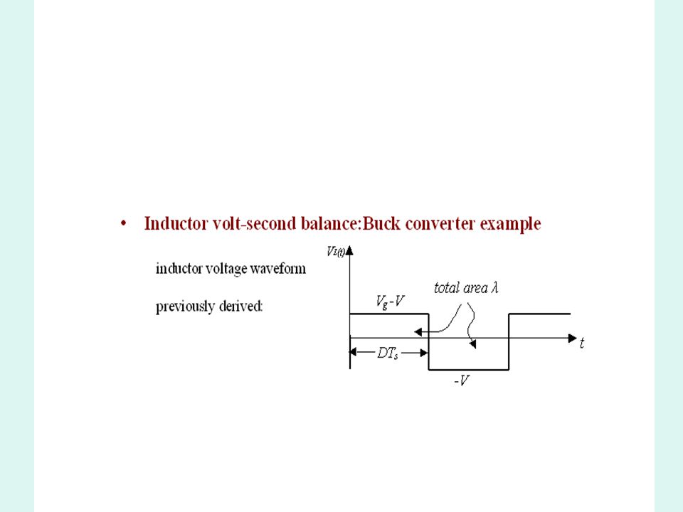
Actual output voltage waveform of buck converter

19
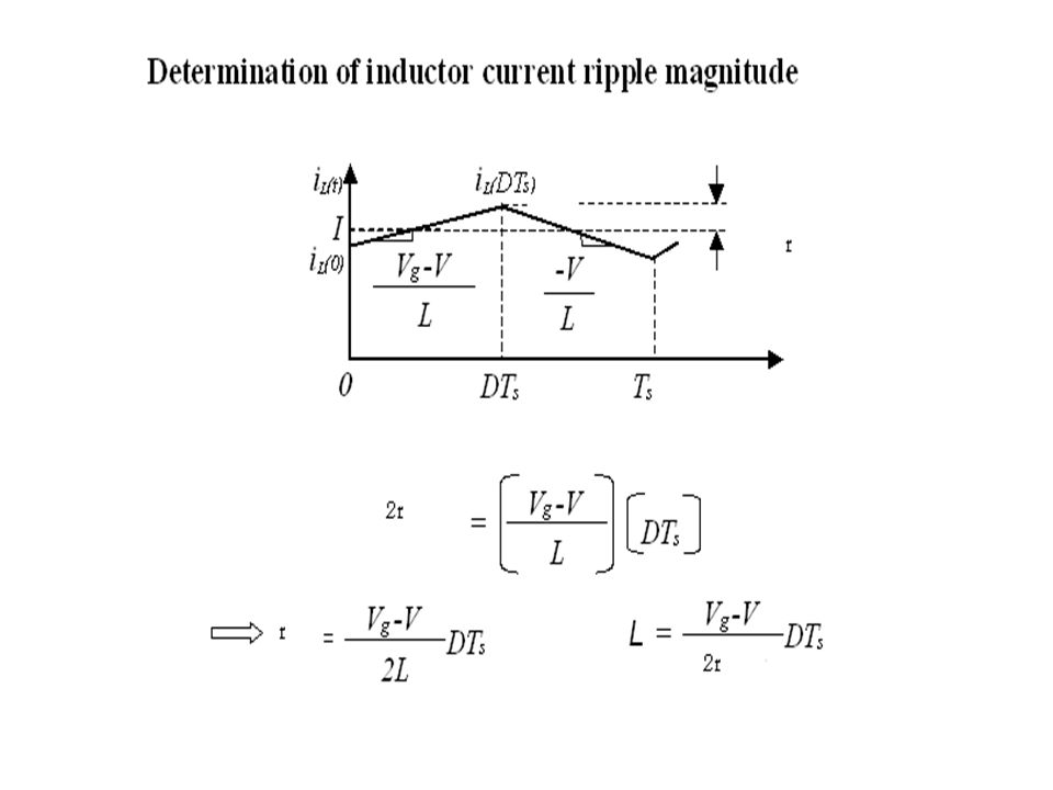
Buck converter analysis: inductor current waveform

20
Inductor voltage and current subinterval 1: switch in position 1

24
Inductor current waveform during start-up transient

27
Boost converter example

28
Boost converter analysis

29
Subinterval 1: switch in position 1

30
Subinterval 2: switch in position 2

31
Inductor voltage and capacitor current waveforms

33
Conversion ratio M(D) of the boost converter
 of the boost converter")
34
Continuous- Conduction- Mode (CCM) and Discontinuous Conduction-Mode (DCM) of boost
 and Discontinuous Conduction-Mode (DCM) of boost")
35
Power Electronics Methods Of Control The output dc voltage can be varied by the following methods. Pulse width modulation control or constant frequency operation. Variable frequency control. 35 Prof. T.K. Anantha Kumar, E&E Dept., MSRIT

36
Pulse Width Modulation
Power Electronics Pulse Width Modulation tON is varied keeping chopping frequency ‘f’ & chopping period ‘T’ constant. Output voltage is varied by varying the ON time tON 36 Prof. T.K. Anantha Kumar, E&E Dept., MSRIT

37
Power Electronics 37 Prof. T.K. Anantha Kumar, E&E Dept., MSRIT

38
Variable Frequency Control
Power Electronics Variable Frequency Control Chopping frequency ‘f’ is varied keeping either tON or tOFF constant. To obtain full output voltage range, frequency has to be varied over a wide range. This method produces harmonics in the output and for large tOFF load current may become discontinuous 38 Prof. T.K. Anantha Kumar, E&E Dept., MSRIT

39
Power Electronics 39 Prof. T.K. Anantha Kumar, E&E Dept., MSRIT

40
Step-down Chopper With R-L Load
Power Electronics Step-down Chopper With R-L Load 40 Prof. T.K. Anantha Kumar, E&E Dept., MSRIT

41
When chopper is ON, supply is connected across load.
Power Electronics When chopper is ON, supply is connected across load. Current flows from supply to load. When chopper is OFF, load current continues to flow in the same direction through FWD due to energy stored in inductor ‘L’. 41 Prof. T.K. Anantha Kumar, E&E Dept., MSRIT

42
Power Electronics Load current can be continuous or discontinuous depending on the values of ‘L’ and duty cycle ‘d’ For a continuous current operation, load current varies between two limits Imax and Imin When current becomes equal to Imax the chopper is turned-off and it is turned-on when current reduces to Imin. 42 Prof. T.K. Anantha Kumar, E&E Dept., MSRIT

43
Power Electronics 43 Prof. T.K. Anantha Kumar, E&E Dept., MSRIT

44
Power Electronics Expressions For Load Current iO For Continuous Current Operation When Chopper Is ON (0 t tON) 44 Prof. T.K. Anantha Kumar, E&E Dept., MSRIT

45
Power Electronics 45 Prof. T.K. Anantha Kumar, E&E Dept., MSRIT

46
Power Electronics 46 Prof. T.K. Anantha Kumar, E&E Dept., MSRIT

47
Power Electronics 47 Prof. T.K. Anantha Kumar, E&E Dept., MSRIT

48
When Chopper is OFF 48 Prof. T.K. Anantha Kumar, E&E Dept., MSRIT
Power Electronics When Chopper is OFF 48 Prof. T.K. Anantha Kumar, E&E Dept., MSRIT

49
Power Electronics 49 Prof. T.K. Anantha Kumar, E&E Dept., MSRIT

50
Power Electronics 50 Prof. T.K. Anantha Kumar, E&E Dept., MSRIT

51
Power Electronics 51 Prof. T.K. Anantha Kumar, E&E Dept., MSRIT

52
Power Electronics 52 Prof. T.K. Anantha Kumar, E&E Dept., MSRIT

53
Power Electronics 53 Prof. T.K. Anantha Kumar, E&E Dept., MSRIT

54
Power Electronics 54 Prof. T.K. Anantha Kumar, E&E Dept., MSRIT

55
Power Electronics 55 Prof. T.K. Anantha Kumar, E&E Dept., MSRIT

56
Power Electronics 56 Prof. T.K. Anantha Kumar, E&E Dept., MSRIT

57
Power Electronics 57 Prof. T.K. Anantha Kumar, E&E Dept., MSRIT

58
Power Electronics 58 Prof. T.K. Anantha Kumar, E&E Dept., MSRIT

59
Power Electronics 59 Prof. T.K. Anantha Kumar, E&E Dept., MSRIT

60
Power Electronics 60 Prof. T.K. Anantha Kumar, E&E Dept., MSRIT

61
Power Electronics 61 Prof. T.K. Anantha Kumar, E&E Dept., MSRIT

62
Principle Of Step-up Chopper
Power Electronics Principle Of Step-up Chopper 62 Prof. T.K. Anantha Kumar, E&E Dept., MSRIT

63
When the chopper is ON, the inductor L is connected across the supply.
Power Electronics Step-up chopper is used to obtain a load voltage higher than the input voltage V. The values of L and C are chosen depending upon the requirement of output voltage and current. When the chopper is ON, the inductor L is connected across the supply. The inductor current ‘I’ rises and the inductor stores energy during the ON time of the chopper, tON. 63 Prof. T.K. Anantha Kumar, E&E Dept., MSRIT

64
Therefore voltage across load is given by
Power Electronics When the chopper is off, the inductor current I is forced to flow through the diode D and load for a period, tOFF. The current tends to decrease resulting in reversing the polarity of induced EMF in L. Therefore voltage across load is given by 64 Prof. T.K. Anantha Kumar, E&E Dept., MSRIT

65
Diode D prevents any current flow from capacitor to the source.
Power Electronics A large capacitor ‘C’ connected across the load, will provide a continuous output voltage . Diode D prevents any current flow from capacitor to the source. Step up choppers are used for regenerative braking of dc motors. 65 Prof. T.K. Anantha Kumar, E&E Dept., MSRIT

66
Expression For Output Voltage
Power Electronics Expression For Output Voltage 66 Prof. T.K. Anantha Kumar, E&E Dept., MSRIT

67
Power Electronics 67 Prof. T.K. Anantha Kumar, E&E Dept., MSRIT

68
Power Electronics 68 Prof. T.K. Anantha Kumar, E&E Dept., MSRIT

69
Power Electronics 69 Prof. T.K. Anantha Kumar, E&E Dept., MSRIT

70
Power Electronics 70 Prof. T.K. Anantha Kumar, E&E Dept., MSRIT

71
Performance Parameters
Power Electronics Performance Parameters The thyristor requires a certain minimum time to turn ON and turn OFF. Duty cycle d can be varied only between a min. & max. value, limiting the min. and max. value of the output voltage. Ripple in the load current depends inversely on the chopping frequency, f. To reduce the load ripple current, frequency should be as high as possible. 71 Prof. T.K. Anantha Kumar, E&E Dept., MSRIT

72
Classification Of Choppers
Power Electronics Classification Of Choppers Choppers are classified as Class A Chopper Class B Chopper Class C Chopper Class D Chopper Class E Chopper 72 Prof. T.K. Anantha Kumar, E&E Dept., MSRIT

73
Class A Chopper 73 Prof. T.K. Anantha Kumar, E&E Dept., MSRIT
Power Electronics Class A Chopper 73 Prof. T.K. Anantha Kumar, E&E Dept., MSRIT

74
When chopper is ON, supply voltage V is connected across the load.
Power Electronics When chopper is ON, supply voltage V is connected across the load. When chopper is OFF, vO = 0 and the load current continues to flow in the same direction through the FWD. The average values of output voltage and current are always positive. Class A Chopper is a first quadrant chopper . 74 Prof. T.K. Anantha Kumar, E&E Dept., MSRIT

75
It is used to control the speed of dc motor.
Power Electronics Class A Chopper is a step-down chopper in which power always flows form source to load. It is used to control the speed of dc motor. The output current equations obtained in step down chopper with R-L load can be used to study the performance of Class A Chopper. 75 Prof. T.K. Anantha Kumar, E&E Dept., MSRIT

76
Power Electronics 76 Prof. T.K. Anantha Kumar, E&E Dept., MSRIT

77
Class B Chopper 77 Prof. T.K. Anantha Kumar, E&E Dept., MSRIT
Power Electronics Class B Chopper 77 Prof. T.K. Anantha Kumar, E&E Dept., MSRIT

78
During the ON period of the chopper, the inductance L stores energy.
Power Electronics When chopper is ON, E drives a current through L and R in a direction opposite to that shown in figure. During the ON period of the chopper, the inductance L stores energy. When Chopper is OFF, diode D conducts, and part of the energy stored in inductor L is returned to the supply. 78 Prof. T.K. Anantha Kumar, E&E Dept., MSRIT

79
Average output voltage is positive.
Power Electronics Average output voltage is positive. Average output current is negative. Therefore Class B Chopper operates in second quadrant. In this chopper, power flows from load to source. Class B Chopper is used for regenerative braking of dc motor. Class B Chopper is a step-up chopper. 79 Prof. T.K. Anantha Kumar, E&E Dept., MSRIT

80
Power Electronics 80 Prof. T.K. Anantha Kumar, E&E Dept., MSRIT

81
Expression for Output Current
Power Electronics Expression for Output Current 81 Prof. T.K. Anantha Kumar, E&E Dept., MSRIT

82
Power Electronics 82 Prof. T.K. Anantha Kumar, E&E Dept., MSRIT

83
Power Electronics 83 Prof. T.K. Anantha Kumar, E&E Dept., MSRIT

84
Power Electronics 84 Prof. T.K. Anantha Kumar, E&E Dept., MSRIT

85
Class C Chopper 85 Prof. T.K. Anantha Kumar, E&E Dept., MSRIT
Power Electronics Class C Chopper 85 Prof. T.K. Anantha Kumar, E&E Dept., MSRIT

86
Class C Chopper is a combination of Class A and Class B Choppers.
Power Electronics Class C Chopper is a combination of Class A and Class B Choppers. For first quadrant operation, CH1 is ON or D2 conducts. For second quadrant operation, CH2 is ON or D1 conducts. When CH1 is ON, the load current is positive. The output voltage is equal to ‘V’ & the load receives power from the source. When CH1 is turned OFF, energy stored in inductance L forces current to flow through the diode D2 and the output voltage is zero. 86 Prof. T.K. Anantha Kumar, E&E Dept., MSRIT

87
Current continues to flow in positive direction.
Power Electronics Current continues to flow in positive direction. When CH2 is triggered, the voltage E forces current to flow in opposite direction through L and CH2 . The output voltage is zero. On turning OFF CH2 , the energy stored in the inductance drives current through diode D1 and the supply Output voltage is V, the input current becomes negative and power flows from load to source. 87 Prof. T.K. Anantha Kumar, E&E Dept., MSRIT

88
Average output voltage is positive
Power Electronics Average output voltage is positive Average output current can take both positive and negative values. Choppers CH1 & CH2 should not be turned ON simultaneously as it would result in short circuiting the supply. Class C Chopper can be used both for dc motor control and regenerative braking of dc motor. Class C Chopper can be used as a step-up or step-down chopper. 88 Prof. T.K. Anantha Kumar, E&E Dept., MSRIT

89
Power Electronics 89 Prof. T.K. Anantha Kumar, E&E Dept., MSRIT

90
Class D Chopper 90 Prof. T.K. Anantha Kumar, E&E Dept., MSRIT
Power Electronics Class D Chopper 90 Prof. T.K. Anantha Kumar, E&E Dept., MSRIT

91
Class D is a two quadrant chopper.
Power Electronics Class D is a two quadrant chopper. When both CH1 and CH2 are triggered simultaneously, the output voltage vO = V and output current flows through the load. When CH1 and CH2 are turned OFF, the load current continues to flow in the same direction through load, D1 and D2 , due to the energy stored in the inductor L. Output voltage vO = - V . 91 Prof. T.K. Anantha Kumar, E&E Dept., MSRIT

92
Average output voltage becomes negative if tON < tOFF .
Power Electronics Average load voltage is positive if chopper ON time is more than the OFF time Average output voltage becomes negative if tON < tOFF . Hence the direction of load current is always positive but load voltage can be positive or negative. 92 Prof. T.K. Anantha Kumar, E&E Dept., MSRIT

93
Power Electronics 93 Prof. T.K. Anantha Kumar, E&E Dept., MSRIT

94
Power Electronics 94 Prof. T.K. Anantha Kumar, E&E Dept., MSRIT

95
Class E Chopper 95 Prof. T.K. Anantha Kumar, E&E Dept., MSRIT
Power Electronics Class E Chopper 95 Prof. T.K. Anantha Kumar, E&E Dept., MSRIT

96
Four Quadrant Operation
Power Electronics Four Quadrant Operation 96 Prof. T.K. Anantha Kumar, E&E Dept., MSRIT

97
Class E is a four quadrant chopper
Power Electronics Class E is a four quadrant chopper When CH1 and CH4 are triggered, output current iO flows in positive direction through CH1 and CH4, and with output voltage vO = V. This gives the first quadrant operation. When both CH1 and CH4 are OFF, the energy stored in the inductor L drives iO through D2 and D3 in the same direction, but output voltage vO = -V. 97 Prof. T.K. Anantha Kumar, E&E Dept., MSRIT

98
Therefore the chopper operates in the fourth quadrant.
Power Electronics Therefore the chopper operates in the fourth quadrant. When CH2 and CH3 are triggered, the load current iO flows in opposite direction & output voltage vO = -V. Since both iO and vO are negative, the chopper operates in third quadrant. 98 Prof. T.K. Anantha Kumar, E&E Dept., MSRIT

99
Power Electronics When both CH2 and CH3 are OFF, the load current iO continues to flow in the same direction D1 and D4 and the output voltage vO = V. Therefore the chopper operates in second quadrant as vO is positive but iO is negative. 99 Prof. T.K. Anantha Kumar, E&E Dept., MSRIT

100
Impulse Commutated Chopper
Power Electronics Impulse Commutated Chopper Impulse commutated choppers are widely used in high power circuits where load fluctuation is not large. This chopper is also known as Parallel capacitor turn-off chopper Voltage commutated chopper Classical chopper. 100 Prof. T.K. Anantha Kumar, E&E Dept., MSRIT

101
Power Electronics 101 Prof. T.K. Anantha Kumar, E&E Dept., MSRIT

102
Capacitor ‘C’ gets charged through VS, C, T2 and load.
Power Electronics To start the circuit, capacitor ‘C’ is initially charged with polarity (with plate ‘a’ positive) by triggering the thyristor T2. Capacitor ‘C’ gets charged through VS, C, T2 and load. As the charging current decays to zero thyristor T2 will be turned-off. With capacitor charged with plate ‘a’ positive the circuit is ready for operation. Assume that the load current remains constant during the commutation process. 102 Prof. T.K. Anantha Kumar, E&E Dept., MSRIT
 by triggering the thyristor T2. Capacitor ‘C’ gets charged through VS, C, T2 and load. As the charging current decays to zero thyristor T2 will be turned-off. With capacitor charged with plate ‘a’ positive the circuit is ready for operation. Assume that the load current remains constant during the commutation process Prof. T.K. Anantha Kumar, E&E Dept., MSRIT.")
103
For convenience the chopper operation is divided into five modes.
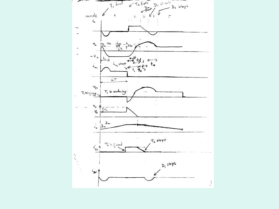
Power Electronics For convenience the chopper operation is divided into five modes. Mode-1 Mode-2 Mode-3 Mode-4 Mode-5 103 Prof. T.K. Anantha Kumar, E&E Dept., MSRIT

104
Mode-1 Operation 104 Prof. T.K. Anantha Kumar, E&E Dept., MSRIT
Power Electronics Mode-1 Operation 104 Prof. T.K. Anantha Kumar, E&E Dept., MSRIT

105
Thyristor T1 is fired at t = 0.
Power Electronics Thyristor T1 is fired at t = 0. The supply voltage comes across the load. Load current IL flows through T1 and load. At the same time capacitor discharges through T1, D1, L1, & ‘C’ and the capacitor reverses its voltage. This reverse voltage on capacitor is held constant by diode D1. 105 Prof. T.K. Anantha Kumar, E&E Dept., MSRIT

106
Power Electronics 106 Prof. T.K. Anantha Kumar, E&E Dept., MSRIT

107
Mode-2 Operation 107 Prof. T.K. Anantha Kumar, E&E Dept., MSRIT
Power Electronics Mode-2 Operation 107 Prof. T.K. Anantha Kumar, E&E Dept., MSRIT

108
Thyristor T2 is now fired to commutate thyristor T1.
Power Electronics Thyristor T2 is now fired to commutate thyristor T1. When T2 is ON capacitor voltage reverse biases T1 and turns if off. The capacitor discharges through the load from –V to 0. Discharge time is known as circuit turn-off time. 108 Prof. T.K. Anantha Kumar, E&E Dept., MSRIT

109
Power Electronics 109 Prof. T.K. Anantha Kumar, E&E Dept., MSRIT

110
This time is called the recharging time and is given by
Power Electronics Capacitor recharges back to the supply voltage (with plate ‘a’ positive). This time is called the recharging time and is given by The total time required for the capacitor to discharge and recharge is called the commutation time and it is given by 110 Prof. T.K. Anantha Kumar, E&E Dept., MSRIT
. This time is called the recharging time and is given by. The total time required for the capacitor to discharge and recharge is called the commutation time and it is given by Prof. T.K. Anantha Kumar, E&E Dept., MSRIT.")
111
Power Electronics At the end of Mode-2 capacitor has recharged to VS and the free wheeling diode starts conducting. 111 Prof. T.K. Anantha Kumar, E&E Dept., MSRIT

112
Mode-3 Operation 112 Prof. T.K. Anantha Kumar, E&E Dept., MSRIT
Power Electronics Mode-3 Operation 112 Prof. T.K. Anantha Kumar, E&E Dept., MSRIT

113
FWD starts conducting and the load current decays.
Power Electronics FWD starts conducting and the load current decays. The energy stored in source inductance LS is transferred to capacitor. Hence capacitor charges to a voltage higher than supply voltage, T2 naturally turns off. 113 Prof. T.K. Anantha Kumar, E&E Dept., MSRIT

114
Power Electronics 114 Prof. T.K. Anantha Kumar, E&E Dept., MSRIT

115
Mode-4 Operation 115 Prof. T.K. Anantha Kumar, E&E Dept., MSRIT
Power Electronics Mode-4 Operation 115 Prof. T.K. Anantha Kumar, E&E Dept., MSRIT

116
Capacitor starts discharging in reverse direction.
Power Electronics Capacitor has been overcharged i.e. its voltage is above supply voltage. Capacitor starts discharging in reverse direction. Hence capacitor current becomes negative. The capacitor discharges through LS, VS, FWD, D1 and L. When this current reduces to zero D1 will stop conducting and the capacitor voltage will be same as the supply voltage 116 Prof. T.K. Anantha Kumar, E&E Dept., MSRIT

117
Power Electronics Mode-5 Operation Both thyristors are off and the load current flows through the FWD. This mode will end once thyristor T1 is fired. 117 Prof. T.K. Anantha Kumar, E&E Dept., MSRIT

119
Power Electronics 119 Prof. T.K. Anantha Kumar, E&E Dept., MSRIT

120
Power Electronics 120 Prof. T.K. Anantha Kumar, E&E Dept., MSRIT

121
Power Electronics Disadvantages A starting circuit is required and the starting circuit should be such that it triggers thyristor T2 first. Load voltage jumps to almost twice the supply voltage when the commutation is initiated. The discharging and charging time of commutation capacitor are dependent on the load current and this limits high frequency operation, especially at low load current. 121 Prof. T.K. Anantha Kumar, E&E Dept., MSRIT

122
Chopper cannot be tested without connecting load.
Power Electronics Chopper cannot be tested without connecting load. Thyristor T1 has to carry load current as well as resonant current resulting in increasing its peak current rating. 122 Prof. T.K. Anantha Kumar, E&E Dept., MSRIT

Similar presentations


>")

>")


 國立雲林科技大學 電子工程系>")


 The objective is to convert a fixed DC voltage to a variable DC voltage It is possible to step up and step down voltage.>")


