Download presentation
Presentation is loading. Please wait.

1
SDL: A Protocol Specification Language Anandi Giridharan Department of Electrical Communication Engineering Indian Institute of Science Bangalore – 560012, India

2
Why specification The size of produced software has increased dramatically. More and more systems are multiprocess and distributed, and they execute in a heterogeneous environment. International market grows, equipment from different manufacturers must be able to communicate with each other. Therefore, the formal methods should be internationally standardized. Telecommunications Software engineers have developed such methods and tools for the development of complex real time software. SDL is an object oriented formal language defined by the ITU−T for specification of complex, real time applications.

3
Specification language specifies the communication protocols either by using formal or graphical notation or both. There are several specification languages: LOTOS (Language of Temporal ordering specifications) ESTELLE (Extended State Transition Language) SDL (Specification and Description Language) SPIN (Simple Promela Interpreter) CPN (Coloured PetriNets)
 ESTELLE (Extended State Transition Language) SDL (Specification and Description Language) SPIN (Simple Promela Interpreter) CPN (Coloured PetriNets).")
4
The Specification and Description Language is a language for the specification and description of systems that has been developed and standardized by ITU-T, the Telecommunication standards sector of the International Telecommunication Union (ITU) SDL has been applied to system analysis and design in many application domains. SDL uses FSMs and its extensions for specification Graphical representation to specify behavior of protocols.

5
Salient Features of SDL well defined set of concepts. unambiguous, clear, precise, and concise specifications thorough basis for analyzing specifications and conformance testing. basis for determining the consistency of specifications. good computer support interface for generating applications without the need for the traditional coding phase. high degree of testability as a result of its formalism for parallelism, interfaces, communication and time. portability, scalability and open specification high degree of reuse because of visual clarity, object oriented concepts, clear interfaces, and abstraction mechanisms. facility for applying optimization techniques improving protocol efficiency.

6
SDL is well suited to be the core of full-scale projects because of its abilities to interface with other languages. unified modeling language (UML) object models, mobile switching center (MSC) use-cases, as well as abstract system notation one (ASN.1), Tests can also be generated from the SDL specification by making a test suite in tree and tabular combined notion (TTCN).
 object models, mobile switching center (MSC) use-cases, as well as abstract system notation one (ASN.1), Tests can also be generated from the SDL specification by making a test suite in tree and tabular combined notion (TTCN)..")
7
SDL Syntax

9
Description of a communication system by SDL structure: a system, block, process, and procedure hierarchy communication: signals with optional signal parameters and channels (or signal routes) behavior: processes or entities data: abstract data types (ADTs) or prede ned data types inheritance: describing relations and specialization
 behavior: processes or entities data: abstract data types (ADTs) or prede ned data types inheritance: describing relations and specialization")
10
It Comprises four main hierarchical levels: System Block Process Procedure

12
Dividing a system into a system, block, and process hierarchy is called partitioning a system. The objectives of partitioning include the following: – hiding information (move details not important in an overview to lower levels) – following natural functional subdivisions – creating modules of intellectually manageable sizes – creating a correspondence with actual software or hardware
 – following natural functional subdivisions – creating modules of intellectually manageable sizes – creating a correspondence with actual software or hardware.")
13
Each SDL process type is defined as a nested hierarchical state machine. SDL processes have separate memory spaces, This is a highly important aspect that dramatically reduces the number of deficiencies and increases robustness. A set of processes can be logically grouped into a block (that is, subsystem). Blocks can be nested inside each other to recursively break down a system into smaller and maintainable encapsulated subsystems. These break-down mechanisms are important for large team development efforts, and SDL simplifies this by also providing clear interfaces between subsystems.
. Blocks can be nested inside each other to recursively break down a system into smaller and maintainable encapsulated subsystems. These break-down mechanisms are important for large team development efforts, and SDL simplifies this by also providing clear interfaces between subsystems..")
14
Static and Dynamic Structure The static structure of a system is defined in terms of blocks and channels. The dynamic structure is defined with the help of the process and the signal route concepts. Communication: SDL has two basic communication mechanisms: asynchronous signals (and optional signal parameters) and synchronous remote procedure calls. Both mechanisms can carry parameters to interchange and synchronize information between SDL processes and with an SDL system and its environment. SDL defines clear interfaces between blocks and processes by means of a combined channel and signal route architecture.
 and synchronous remote procedure calls. Both mechanisms can carry parameters to interchange and synchronize information between SDL processes and with an SDL system and its environment. SDL defines clear interfaces between blocks and processes by means of a combined channel and signal route architecture..")
15
SDL defines time and timers in a clever and abstract manner. Time is an important aspect in all real-time systems but also in most distributed systems. An SDL process can set timers that expire within certain time periods to implement time-outs when exceptions occur but also to measure and control response times from other processes and systems. When an SDL timer expires, the process that started the timer receives a notification (signal) in the same way as it receives any other signal.
 in the same way as it receives any other signal..")
16
Behavior The dynamic behavior in an SDL system is described in the processes. Processes in SDL can be created at system start or created and terminated at run time. Each instance has a unique process identifier (Pid). This makes it possible to send signals to individual instances of a process.
. This makes it possible to send signals to individual instances of a process..")
17
Components of a communication system structure in SDL

18
System components & Block components

19
SDL Structure

20
Data Types SDL accepts two ways of describing data, abstract data type (ADT) and ASN.1. The set of predefined sorts in SDL makes it possible to work with data in SDL in a traditional way. – Integer – Real – natural – Boolean – Character – Duration – Time – Charstring – PId

21
Abstract Data Types a data type with no specified data structure. it specifies a set of values, a set of operations allowed, and a set of equations that the operations must fulfill. Tsimple to map an SDL data type to data types used in other high-level languages. A new data type is often introduced with new operators on existing datatypes Each data type is associated with a set of literals and operators, for example, boolean literals (true or false), and its operators are and, not, or, and xor.
, and its operators are and, not, or, and xor..")
22
Abstract Data Types – Example Example ADT: NEWTYPE Boolean literal True, False; operators "not" : Boolean Boolean; "=" : Boolean, Boolean ! Boolean;...... axioms "not"(True) == False; "not"(False) == True; "="(True, True) == True; "="(True, False) == False;..... ENDNEWTYPE Boolean
 == False; not (False) == True; = (True, True) == True; = (True, False) == False;..... ENDNEWTYPE Boolean.")
23
Communication paths

24
Example – Communication Path

25
It consists of a system, two blocks B1 and B2, two processes in block B1 and B2 (not shown in the gure), each process pr1 and pr2 consists of several states, transitions and procedures, and each procedure with several states and transitions. The channels C1 and C3 are used to communicate with the environment by the blocks 1 and 2, respectively, and the channel C2 is used to communicate between the blocks 1 and 2. The signal routes R1 to R4 are used to communicate among the processes of a block and the environment. The signal routes R2 and R3 are used for communication among the processes pr1 and pr2. The signals 'a' and 'b' are used to communicate with the environment using the chan- nels C1 and C3, respectively. Similarly, signals X and Y are used in the block B1 which communicate with other blocks via signal routes R1 and R4, respectively. A set of signals [W,Z] and [J,K] are used to communicate among the processes in the block B1 via signal routes R2 and R3, respectively.

26
Examples of SDL based protocol specifications QA protocol

27
QA Structure and package

28
Package of QA protocol- 6 signals..

29
1 Block of QA protocol

30
3 process of QA protocol

31
Q entity-Process

32
Service Provider- Process

33
A entity-process

34
QA protocol A QA service provider provides the service in the form of answers from the user A to the questions framed by the user Q. The sequence of operations of the protocol is as follows: signal 'Q-req' is sent to the protocol entity of user Q from the user Q. signal 'Q-req' is forwarded as signal 'D-req' to service provider protocol entity. QA service provider (provides connectionless service) forwards the 'D-req' signal as 'D-ind' signal to the user A's protocol entity. signal 'D-ind' is sent as signal 'Q-ind' to the protocol entity of user A user A generates the signal 'A-req' as an answer to 'Q-req' and sends it to the service provider signal 'A-req' is sent as signal 'D-req' to the service provider protocol entity QA service provider sends signal 'D-ind' to protcol entity of user Q Protocol entity at user Q forwards this as an 'A-ind' to the user Q
 forwards the D-req signal as D-ind signal to the user A s protocol entity. signal D-ind is sent as signal Q-ind to the protocol entity of user A user A generates the signal A-req as an answer to Q-req and sends it to the service provider signal A-req is sent as signal D-req to the service provider protocol entity QA service provider sends signal D-ind to protcol entity of user Q Protocol entity at user Q forwards this as an A-ind to the user Q.")
35
Protocols Spec in SDL - QA protocol The components of the QA protocol are as follows: one block called QA protocol. two processes called 'Qentity' and 'Aentity' representing the user Q and user A, re- spectively three bidirectional signal routes represented as 'Qi', 'Ai', and 'CL' are used in the protocol model. six signals are declared using the keyword 'SIGNAL': Dreq, Dind, Qreq, Qind, Aind, and Areq. Dreq (from process 'Qentity' to 'Aentity' and vice versa) and Dind (from process 'Qentity' to 'Aentity' and vice versa) are the signals routed on route 'CL'. 'Aind' (from process Qentity to user Q) and 'Qreq' (from user Q to process Qentity) are the signals routed on routes 'Qi'.
 and Dind (from process Qentity to Aentity and vice versa) are the signals routed on route CL . Aind (from process Qentity to user Q) and Qreq (from user Q to process Qentity) are the signals routed on routes Qi ..")
36
Xon-Xoff protocol primitive flow control protocol a receiver controls the data transfer by signaling the sender This protocol uses three types of PDUs: Data PDU: this is sent to the receiver PE (Protocol Entity) by the sender PE, it contains the user data; Suspend PDU: it is sent to the sender PE by the receiver PE to signal the sender to stop sending Data PDUs; Resume PDU: it is sent to the sender PE by the receiver PE to signal the sender to resume sending Data-PDUs.
 by the sender PE, it contains the user data; Suspend PDU: it is sent to the sender PE by the receiver PE to signal the sender to stop sending Data PDUs; Resume PDU: it is sent to the sender PE by the receiver PE to signal the sender to resume sending Data-PDUs.")
37
Xon-Xoff protocol The sequence of operations in this protocol are as follows the sender sends the Data PDU along with the signal 'LDreq(pdu)' to the receiver The receiver sends either Resume PDU or Suspend PDU to the sender along with the signal 'LDreq(pdu)' (sends the resume signal if it has received minimum Data PDUs or sends the suspend signal if it has received maximum Data PDUs set for the sender). Signal 'LDreq(pdu)' from the receiver is received at the sender.
 from the receiver is received at the sender..")
38
X on Xoff- system

39
Xon Xoff- Blocks

40
Xon Xoff- sender Process

41
Xon Xoff- Receiver Process

42
The sender protocol entity Variable declarations: d is the data to be transmitted, which is declared as octet-string (string of length 8 bits), p is declared as a pdu type (contains type of PDU and the data). These declarations are given in the package shown by dotted lines as the new data types. states of the sender: Go, Waiting and a combination of Go and waiting Signals with parameters: output signal LDreq(p), an input signal LDreq(p1), and Dreq(d) from the sender. PDU type (ptype): Data, resume and suspend (p!ptype := Data, indicates that the Data is assigned to member ptype of pdu; the operator ' !' is used to access the member of the structure).
, an input signal LDreq(p1), and Dreq(d) from the sender. PDU type (ptype): Data, resume and suspend (p!ptype := Data, indicates that the Data is assigned to member ptype of pdu; the operator ! is used to access the member of the structure)..")
43
The receiver protocol entity variable declarations: d as octet string; p and p1 as pdu data type; n, max and min as integers (n=counter, min=minimum number of PDUs, max= maximum number of PDUs); buf is a FIFObu er data type. states of the receiver: Go and Stopped. signals with parameters: output signals LDreq(p1) and Dind(d); high priority input signal LDreq(p). FIFObuffer: the bu er, buf, will be appended with the received octet string from the sender (the operator '//' indicates appending the bu er, the operator "/=" indicates not equal, the function Substring nds a string from buf). PDU type (ptype): resume and suspend PDUs are generated by the protocol entity.
 and Dind(d); high priority input signal LDreq(p). FIFObuffer: the bu er, buf, will be appended with the received octet string from the sender (the operator // indicates appending the bu er, the operator /= indicates not equal, the function Substring nds a string from buf). PDU type (ptype): resume and suspend PDUs are generated by the protocol entity..")
44
Alternating Bit protocol Is one bit sliding window protocol. It transmits packets with sequence numbers either 0 or 1 in a reliable manner. The protocol consist of Sender, Receiver, Data medium, Ack_medium processes 2 channels with FIFO characteristics Both channels processes are modeled to lost messges.

45
Block of Alternating Bit Protocol

46
Alternating Bit Protocol One block which has sender and receiver entities along with the channel process (ack and data medium). a package defining all the signals used in the protocol model DataS_0 and DataS_1 are the data sent from the sender to data medium process; DataR_0 and DataR_1 are the data sent from the data medium to receiver process; AckS_0 and AckS_1 are the acknowledgments from ack medium to sender; AckR_0 and AckR_1 are the acknowledgments from receiver to ack medium; Receiver Ready, Receive, and Deliver are signals exchanged between receiver and upper layer processes. two communication channels: ack loss signal and data loss signal connects the system to environment. input signals from the environment: Lose Data and Lose Ack.

47
Alternating Bit Protocol

49
The block consists of the following processes ULsenderP: upper layer sender process ULReceiver: upper layer receiver process DataMedium: provides service to transmit data from sender to receiver SenderP: sender process to transmit the frames ReceiverP: receiver process to receive the data and deliver to upper layer process as well as acknowledge the received data. AckMedium: provides service to transmit the acknowledgments received from the re- ceiver to sender.

50
Sender Process of ABP

51
Receiver Process of ABP

52
Sender & Receiver Process of ABP Sender Process: data declarations: Timer1 states: Wait_0, Wait_1, Idle_0, Idle_1 inputs: AckS_0, AckS 1, Send outputs: DataS_0, DataS_1, Sender_Ready Reciever Process: states: Wait_0, Wait_1, Idle_0, Idle_1 inputs: DataR_1, DataR_0, Receive outputs: AckR_0, AckR_1, Deliver, Receiver Ready

53
Upper Layer of sender of ABP

54
Upper Layer of receiver of ABP

55
Data Medium Process

56
Ack Medium Process

57
Specifications of a bridge connecting CSMA/CD and CSMA/CA protocols

58
This scenario is modeled as a system comprising of three blocks, variable declarations and signal routes The components defined in the system are as follows: It has three blocks: bridge, csma/cd and csma/ca. a package defining all the signals used in the block and process speci cations is given in next slide It has four channels connecting the blocks: c1, c2, c3 and c4 where each carries different signals which are defined in the package input signals from the environment: user 1 and user 2 are the users of csma/cd block; and, user3 and user4 are users of csma/ca.

59
Specifications of a bridge connecting CSMA/CD and CSMA/CA protocols

60
The bridge block consists of the following: process: bridge p signal routes: p1 and p2 which are connected to channels c1 and c2 respectively input signals carried by p1 and p2 are: fpacket1,res and end pac output signals carried by p1 are: packet1 bridge, req chan state and end packet output signals carried by p2 are: packet bridge, req chan state and end packet.

61
The block CSMA/CA Processes: channel csma_ca: maintains the channel status and forwards the data to bridge and other node(s) csma_ca_3: implements the csma/ca operations for user3 csma_ca_4: implements the csma/ca operations for user4 pac_gen: generates packets according to input from environment signal routes: p1, p2, p3, p4 and p5 each carrying the signals as indicated Signals from the block are routed to other blocks by using channels c1 and c4
 csma_ca_3: implements the csma/ca operations for user3 csma_ca_4: implements the csma/ca operations for user4 pac_gen: generates packets according to input from environment signal routes: p1, p2, p3, p4 and p5 each carrying the signals as indicated Signals from the block are routed to other blocks by using channels c1 and c4")
62
The block CSMA/CA

63
The block CSMA/CD Processes: channel csma_cd: maintains the channel status and forwards the data to bridge and other node(s) csma_cd_1: implements the csma/cd operations for user1 csma_cd_2: implements the csma/ca operations for user2 pac_gen: generates packets according to input from environment signal routes: p1, p2, p3, p4 and p5 each carrying the signals signals from the block are routed to other blocks by using channels c2 and c3
 csma_cd_1: implements the csma/cd operations for user1 csma_cd_2: implements the csma/ca operations for user2 pac_gen: generates packets according to input from environment signal routes: p1, p2, p3, p4 and p5 each carrying the signals signals from the block are routed to other blocks by using channels c2 and c3")
64
The block CSMA/CD

65
Process diagram of Bridge_p

67
Process diagram of csma_ca channel

69
Process diagram of csma_ca_3 process

70
Process diagram of pac_gen process

71
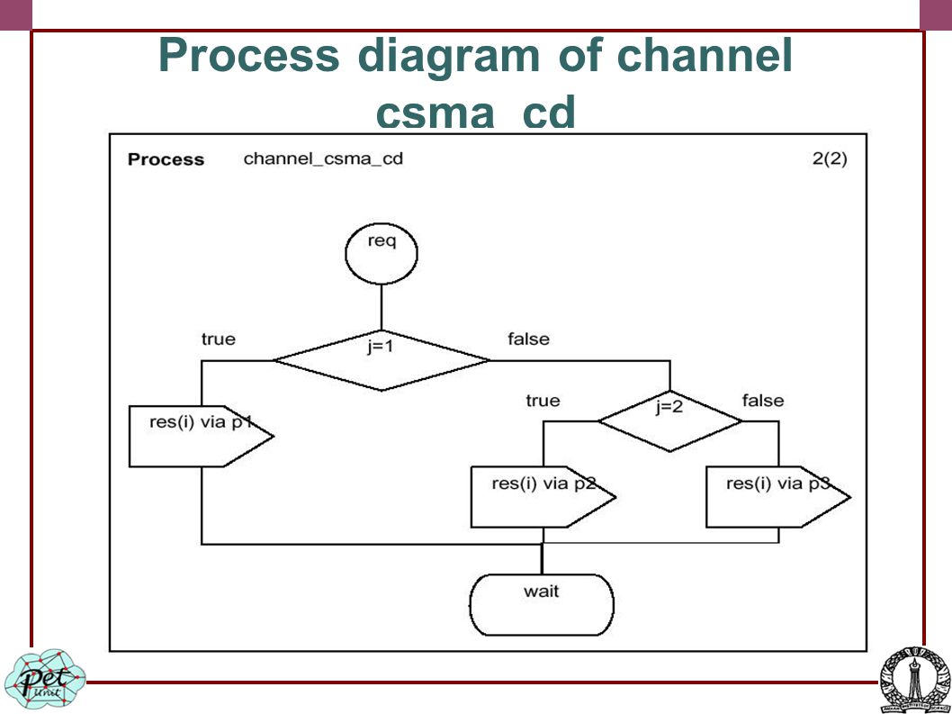
Process diagram of channel csma_cd

73
Process diagram of channel csma_cd_2 process

74
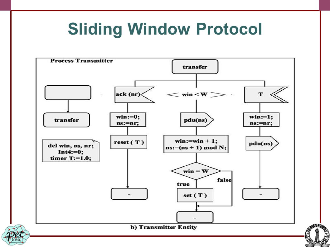
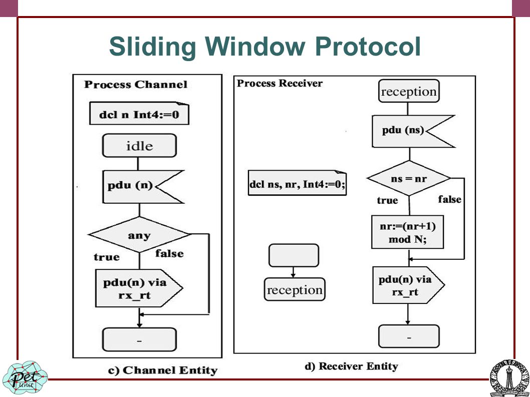
Sliding Window Protocol

77
SDL Specifications of TCP Model consists of three processes variable declarations signal package two signal routes signals: Startsim, ACK1, ACk, packet, thr, packet1 and packet junk A package p in which all the signals used in the block are defined

78
SDL Specifications of TCP

79
Transmitter Process of TCP

80
Channel1 process of TCP

81
Receiver Process of TCP

82
Simulation model representing the simulated network in one SDL system

83
Link modeling

84
OSPF

87
BGP A router will select the "best BGP" route when there are multiple BGP route possibilities of the same speci city. It goes (basically) Route specificity and reachability and reachability BGP weight metric MED (Multi exit discriminator) BGP local_pref metric Internally originated vs. Externally originated AS-PATH (Autonomous System PATH) length
 Route specificity and reachability and reachability BGP weight metric MED (Multi exit discriminator) BGP local_pref metric Internally originated vs. Externally originated AS-PATH (Autonomous System PATH) length.")
88
SDL Model Following are different states of BGP FSM or BGP process for its peers: IDLE: State when BGP peer refuses any incoming connections CONNECT: State in which BGP peer is waiting for its TCP connection to be completed. ACTIVE: State in which BGP peer is trying to acquire a peer by listening and accepting TCP connection. OPENSENT: BGP peer is waiting for OPEN message from its peer OPENCONFIRM: BGP peer is waiting for KEEPALIVE or NOTIFICATION message from its peer. ESTABLISHED: BGP peer connection is established and exchanges UPDATE, NOTI- FICATION, and KEEPALIVE messages with its peer.

89
MPLS SDL based representation of a 4-node Topology,

90
MPLS SDL based representation of BGP Speaker using Block type

91
MPLS simulation manger process

92
MPLS operation Label Creation and Distribution Before any traffic begins the routers make the decision to bind a label to a specific FEC and build their tables In LDP, downstream routers initiate the distribution of labels and the label/FEC binding In addition, traffic-related characteristics and MPLS capabilities are negotiated using LDP A reliable and ordered transport protocol should be used for the signaling protocol. LDP uses TCP. Table Creation On receipt of label bindings each LSR creates entries in the label information base (LIB) The contents of the table will specify the mapping between a label and an FEC.
 The contents of the table will specify the mapping between a label and an FEC..")
93
MPLS operation Label-Switched Path Creation LSPs are created in the reverse direction to the creation of entries in the LIBs Label Insertion/Table Lookup The first router LER1 uses the LIB table to find the next hop and request a label for the specific FEC Subsequent routers just use the label to nd the next hop. Once the packet reaches the egress LSR (LER4), the label is removed and the packet is supplied to the destination.
, the label is removed and the packet is supplied to the destination..")
94
MPLS Operation

95
MPLS operation Packet Forwarding examining the path of a packet as it to its destination from LER1, the ingress LSR, to LER4, the egress LSR LER1 may not have any labels for this packet as it is the first occurence of this request. In an IP network LER1 will initiate a label request toward LSR1. Each intermediary router will receive a label from its downstream router starting from LER4 and going upstream till LER1 LER1 will insert the label and forward the packet to LSR1 Each subsequent LSR will examine the label in the received packet, replace it with the outgoing label and forward it. When the packet reaches LER4, it will remove the label because the packet is departing from an MPLS domain and deliver it to the destination

96
MPLS operation

97
Other protocol specification languages SPIN (Simple ProMeLa Interpreter) Estelle LOTOS (Language Of Temporal Ordering Specifications) CPN (Colored PetriNets) Uppaal UML (Unified Modeling Language)
 Estelle LOTOS (Language Of Temporal Ordering Specifications) CPN (Colored PetriNets) Uppaal UML (Unified Modeling Language)")
Similar presentations


 BEng (Essex, UK)>")


 Chapter 20 IP Datagrams and Datagram Forwarding.>")
 Andres Rengifo Copyright 2008.>")


 is a product of the Open Systems Interconnection effort at the International Organization for Standardization.>")