Download presentation
Presentation is loading. Please wait.

1
HEP Experiments Detectors and their Technologies Sascha Marc Schmeling CERN

2
Overview Introduction and Concepts Properties of Particles –Are they measurable? –If yes, how? HEP Detectors @CERN –Main Sub-Detectors –Infrastructure

3
Studying Interactions by scattering by annihilation and the production of new particles all interactions are produced in –Colliding Beam Experiments or –Fixed Target Experiments

4
Ideal Detectors? In an ideal detector, one could record the full interaction, capture and measure all properties of all emerging particles, and by this reconstruct the complete event. This would give us the power to compare the interaction directly to theoretical predictions without most uncertainties.

5
Particle Properties Which properties does a particle have? –energy –momentum –charge –mass –life time –spin –decay modes And which of those are measurable?

6
Particle Properties Which properties can we derive?

7
Particle Properties charge lifetime

8
Measuring Particle Properties momentum velocity time of flight energy calorimeter

9
Measurement Principles Measurement occurs via the interaction (again…) of a particle with the detector (material) –creation of a measureable signal Ionisation Excitation/Scintillation Change of the particle trajectory –curving in a magnetic field, energy loss –scattering, change of direction, absorption p e-e- p e-e- p p
 of a particle with the detector (material) –creation of a measureable signal Ionisation Excitation/Scintillation Change of the particle trajectory –curving in a magnetic field, energy loss –scattering, change of direction, absorption p e-e- p e-e- p p ")
10
Which particles can be detected? Charged Particles Neutral Particles Different particle types interact very differently with the detector material.

11
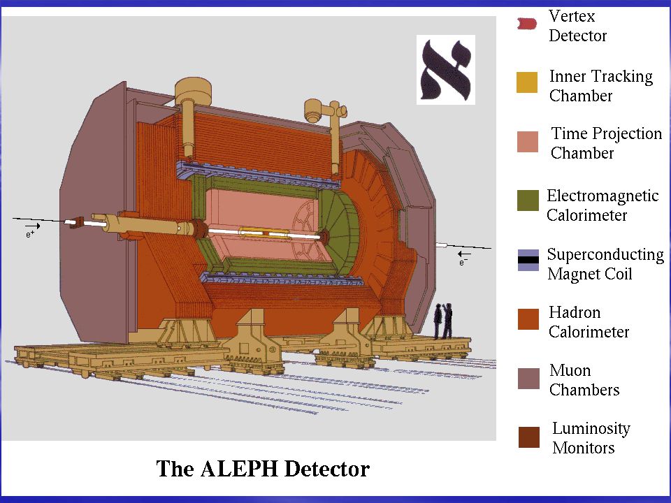
A Typical Detector Concept Interaction point Precision vertex detector tracking detector Magnetic spectrometer Electromagnetic calorimeter Hadronic calorimeter Muon detectors

12
Ingredients Tracking Subsystem Electromagnetic Calorimeter Hadronic Calorimeter Muon System

13
Passage of Particles Electrons Photons Hadrons Muons Mesons

14
Tracking Detectors measure the tracks of emerging particles determine –charge and –momentum in connection with a magnetic field tracks are reconstructed from measured space-points do not use dense material!

15
How do tracking detectors work? two main flavors –ionization detectors Geiger-Müller counter MWPC TPC silicon detectors –scintillation detectors Multi-Wire Proportional Chamber Time Projection Chamber

16
t = 0 Ionization Counters + HV signal cathode Anode Wire Gas-filled tube - - - - - + + + + + - - - - - + + + + + t = t 1

17
Tracking Realization: wire chamber (MWPC) Nobel prize: G.Charpak, 1992 Anode wires Cathode: pads or wires x y
 Nobel prize: G.Charpak, 1992 Anode wires Cathode: pads or wires x y")
18
MWPC ITC (ALEPH) Inner Tracking Chamber
 Inner Tracking Chamber")
19
Time Projection Chamber Gas-filled cylinder Anode Wires MWPC gives r, MWPC gives r, E B - - - - - - + + + + + + - - - - - - - z = v drift t

20
TPC ALICE TPC sector detail

21
ALEPH TPC

22
Limitations Precision limited by wire distance Error on space point d cannot be reduced arbitrarily! Uncertainties on space pointsUncertainties on track origin and momentum

23
Step forward: Silicon Microstrip Detectors Now precision limited by strip distance 10 - 100 m Now precision limited by strip distance 10 - 100 m Creation of electron-hole pairs by ionising particle Creation of electron-hole pairs by ionising particle Same principle as gas counters Silicon wafers, doped 0.2 - 0.3 mm

24
Silicon Microstrip detectors... ALEPH VDET OPAL VDET Future ATLAS tracking detector

25
Increase in precision 0 1cm x =Beam crossing point

26
Mean Lifetime of tau =290 x 10 -15 sec !! --> c = 87 m !?

27
Scintillation Detectors Photomultiplier: converts light into electronic signal Scintillating material Scintillating material PM Total reflection Put many fibers close to each other --> make track visible

28
Calorimeters Basic principle: –In the interaction of a particle with dense material all/most of its energy is converted into secondary particles and/or heat. –These secondary particles are recorded eg. Number, energy, density of secondaries this is proportional to the initial energy

29
Electromagnetic Showers Block of Matter, e.g. lead Lead atom

30
How to measure the secondary particles? 1. With sampling calorimeters: Dense blocks, such as lead Detectors, such as wire chambers, or scintillators Sandwich structure ! Total amount of signals registered is proportional to incident energy. But has to be calibrated with beams of known energy! Sandwich structure ! Total amount of signals registered is proportional to incident energy. But has to be calibrated with beams of known energy!

31
Sampling Calorimeters

33
ALEPH ECAL pions electron

34
muons photons

35
How to measure the secondary particles? 2. With homogenous calorimeters, such as crystal calorimeters: signal photons Photo diode Crystal (BGO, PbWO 4,…)
.")
36
Hadronic calorimeters Hadronic particles (protons, neutrons, pions) can traverse the electromagnetic calorimeters. They can also interact via nuclear reactions ! Usually: Put again a sampling calorimeter after the ECAL Dense blocks, such as iron, uranium Detectors, such as wire chambers, or scintillators Sandwich structure ! Total amount of signals registered is proportional to incident energy. Same energy lost in nuclear excitations! Has to be calibrated with beams of known energy! Sandwich structure ! Total amount of signals registered is proportional to incident energy. Same energy lost in nuclear excitations! Has to be calibrated with beams of known energy!

37
ALEPH iron

38
Particle Identification Basic principles: –via different interaction with matter (see previous transparencies) –by measuring the mass from the decay products –by measuring the velocity and independently (!) the momentum –Observables sensitive to velocity are mean energy loss Cherenkov radiation
 –by measuring the mass from the decay products –by measuring the velocity and independently (!) the momentum –Observables sensitive to velocity are mean energy loss Cherenkov radiation")
39
Mean Energy Loss Particles which traverse a gas loose energy, e.g. by ionization E lost amount of ionization size of signals on wires E lost / path length = func( particle-velocity v/c ) Bethe-Bloch formula Note : if plotted as a function of v and not p all the bands would lie on top of each other!
 Bethe-Bloch formula Note : if plotted as a function of v and not p all the bands would lie on top of each other!.")
40
Cherenkov Radiation Particles which in a given medium travel faster than the speed of light in that medium emit radiation: Cherenkov radiation c 0 = speed of light in vacuum Cherenkovlight wavefront

41
HEP Experiments @CERN All these concepts have been put together and realized in large detector systems Examples at LEP –ALEPH, OPAL, L3, DELPHI Fixed Target –NA48 Future experiments at LHC –ATLAS, CMS, LHCb, ALICE

44
ATLAS See http://pdg.lbl.gov/atlas/index.html

45
See http://cmsinfo.cern.ch/Welcome.html/

46
Infrastructure experiments are not only detectors you need –possibilities to control the detectors –possibilities to take the data out and record it –possibilities to analyze the recorded data –…

Similar presentations


 - A specialized detector system dedicated to the search for Centauros and Strangelets in the baryon dense,>")


E (eV) Soft x-rays 10100 X-rays 0.110 K Soft gamma rays 0.0011 M Hard gamma.>")

 Gas filled detectors a) Ionization chambers b) Proportional counters c) Multiwire chambers d) Time projection.>")
 At HERA high energetic electrons (e) collide with high energetic protons (P). The ZEUS detector measures the properties of the particles.>")
 Why measure energy ? I) Not always practical to measure momentum. An important contribution.>")