Download presentation
Presentation is loading. Please wait.

1
Determining the Rotary Inertia by Use of Torsion Pendulum
11#2015

2
Objective To measure spring's torsion coefficient K.
To measure the moment of inertia of several objects, then compare experimental values with theoretical values and calculate percentage error. To verify the parallel axis theorem by placing movable masses at different positions of the metal rod.

3
THEORY 1. Torsion pendulum system

4
2. Relation between moment of inertia and spring's torsion coefficient, time period
For symmetrical objects, the theoretical values of moment of inertia are obtained by calculation. In the experi-ment, assuming the spring's torsion coefficient is constant, the experimental values of moment of inertia are obtained by only measuring the period T .

5
3. Parallel axis theorem In physics, the parallel axis theorem can be used to determine the moment of inertia of a rigid object about any axis, given the moment of inertia of the object about the parallel axis through the object's centre of mass and the perpendicular distance between the axes. Let I0 denote the moment of inertia of the object about the centre of mass, m the object's mass and x the perpendicular distance between the two axes. Then the moment of inertia about the new axis z is given by

6
APPARATUS Torsion pendulum, object stage, solid sphere, solid plastic cylinder, hollow metal cylinder, metal rod with movable masses, Vernier caliper, period tester

7
EXPERIMENT PROCEDURE 1. Using the vernier caliper, measure the diameter of solid plastic cylinder, the inner diameter and outer diameter of hollow metal cylinder, the diameter of solid sphere. Meanwhile, record the given mass of objects into the table. They are written on the surface of objects or on the blackboard. 2. Adjusting the torsion pendulum in order to place the air bubble in the center of the levelling instrument. 3. Fixing metal object stage and adjusting the photoelectric detector. Place the blocked-light pole in the middle of the gap to block the light. Then measure the time T0 of 10 periods.

8
EXPERIMENT PROCEDURE 4. Placing the solid plastic cylinder on the object stage and measuring the time T1 of 10 periods.

9
EXPERIMENT PROCEDURE 5. Replacing solid plastic cylinder by hollow metal cylinder, then measure the time T2 of 10 periods. 6. Replacing metal object stage and hollow metal cylinder by solid sphere, then measure the time T3 of 10 periods. 7. Fixing the center of metal rod on the axis, then measure the time T4 of 10 periods.

10
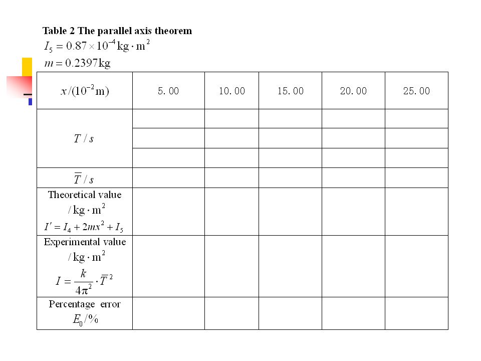
EXPERIMENT PROCEDURE 8. Placing two movable masses on the metallic rod at different radii from the axis of rotation symmetrically. The distance x is 5.00 cm, cm, cm, cm and cm, respectively,we will measure the time of 5 periods.

11
EXPERIMENT NOTICE The photoelectric detector should be placed on equilibrium position of the blocked-light pole. They are separate. The twist angle should be kept constant. It is about 60ºin each experiment. The torsion pendulum is always horizontal. The metal object stage and objects are fixed tightly on the axis. The objects on the object stage are not slant.

12
DATA Table 1 Moment of inertia

Similar presentations


.>")


 Volume Center.>")


