Download presentation
Presentation is loading. Please wait.

1
LIGHT Everything written in black has to go into your notebook
Everything written in blue should already be in there

2
WHAT IS LIGHT? Light is a form of energy that travels away from the source producing it at a speed of 3 x 10⁸ m s-1

3
Transparent: allows light to pass through it, and can see clearly through it e.g. glass
Translucent: allows light to pass through it, but cannot see clearly through it e.g. frosted glass Opaque: does not allow light to pass through it e.g. aluminium

4
Light Travels in Straight Lines
Light travels in straight lines. This can be seen in the following examples Laser Beam of light from a searchlight It can also be shown using pieces of cardboard with a small hole in the middle and a length of thread

5
A plane mirror is a flat mirror

6
Plane Mirror (diagram on page 1)
Normal Incident ray Reflected ray Angle of incidence Angle of reflection i r Plane Mirror

7
LAWS OF REFLECTION OF LIGHT
1. The incident ray, the normal and the reflected ray all lie in the same plane 2. The angle of incidence is equal to the angle of reflection (i = r)
")
8
HOW IS AN IMAGE FORMED IN A PLANE MIRROR (diagram page 2)
")
9
Properties of an image in a plane mirror
The image is: Laterally inverted E.g. your right hand appears as a left hand The “ambulance” sign Erect Virtual Same size as object

10
Uses of Plane Mirrors Make up mirror The periscope

11
Diagram page 3

12
A virtual image cannot be formed on a screen
A real image can be formed on a screen

13
Experiment to prove the angle of incidence equals the angle of reflection (page 26)
")
14
Diagram on page 26 Plane mirror Sheet of paper i r Pins

15
Reflection is the bouncing of light off an object

16
Experiment to prove the angle of incidence equals the angle of reflection (written up in homework copy)
")
17
Diagram (in homework copy)
Finder pin Plane mirror Object pin O M I

18
The following goes in your homework copy
Method Set up the apparatus as in the diagram Move the finder pin in and out behind the mirror until there is no parallax between the object and its image in the mirror

19
3. Measure the distance from the object to the mirror (OM), and the distance from the mirror to the image pin (MI) Result OM and MI are equal Conclusion The image is as far behind the mirror as the object is in front of it

20
Spherical Mirrors (page 4)
CONVEX CONCAVE

21
The line from the centre of curvature to the pole is called the principal axis

22
Rules for Ray Diagrams for Concave Mirror
1. A ray travelling parallel to the principal axis is reflected through the focus 2. A ray travelling through the focus is reflected parallel to the principal axis 3. For a ray which strikes the pole, angle i will be equal to angle r

23
Top of page 5 “In parallel, out through the focus”
“In through the focus, out parallel”

24
Uses of concave mirrors
Spotlights Reflectors in car headlights Shaving and make-up mirrors

25
Uses of convex mirrors Shops (to deter shoplifters) Buses
Dangerous bends in roads They give a wide field of view

26
The Mirror Formulae u = distance from object to mirror
v = distance from image to mirror f = focal length

27
Example 2 When an object is placed 16 cm in front of a concave mirror of focal length 8 cm, an image is formed. Find the distance of the image from the mirror and say whether it is real or virtual.

28
v = 16 cm

29
It is a real image since the object is outside f

30
Magnification m =

31
Example 3 (HL) An object is placed 20 cm from a concave mirror of focal length 25 cm. Find the position, magnification and nature of the image.

32
v = 100 cm

33
It is a virtual image since the object is inside f

34
m = m = 5

35
Example 4 (HL) A concave mirror of focal length 10 cm forms an erect image four times the size of the object. Calculate the object distance and its nature.

36
u = 7.5 cm

37
It is a virtual image since the object is inside f

38
Experiment to Measure the Focal Length of a Concave Mirror (page 30)
")
39
CROSS THREADS RAY BOX CONCAVE MIRROR SCREEN Diagram page 30

40
Light (2) Refraction and Lenses
 Refraction and Lenses")
41
Refraction of light is the bending of light as it goes from one optical medium to another
A medium is a substance; e.g. glass, air etc.

42
Incident ray i r Refracted ray Glass block

43
Less dense to more dense: bends towards normal
(Page 12, under diagram) Less dense to more dense: bends towards normal More dense to less dense: bends away from normal
 Less dense to more dense: bends towards normal. More dense to less dense: bends away from normal.")
44
The Laws of Refraction of Light
1. The incident ray, the normal and the refracted ray all lie in the same plane where n is a constant This is called Snell’s Law

45
Experiment to Verify Snell’s Law and determine the refractive index of glass (diagram page 27)
Pins Glass Block Sheet of paper

46
Enter the following results at the top of page 28, and draw the corresponding graph underneath

47
Your graph in page 28 should look like this
Sin i Sin r

48
Real and Apparent Depth (page 12)
A swimming pool appears to be less deep than it actually is, due to refraction at the surface of the water We can calculate the refractive index of a liquid by using n =

49
Critical angle The critical angle is the angle of incidence in the denser medium when the angle of refraction is 90˚

50
Total Internal Reflection
This occurs when the angle of incidence in the denser medium exceed the critical angle The ray of light is refracted away from the normal As i is increased so is r Eventually r = 90˚ At this point i has reached the ‘critical angle’ If i is increased beyond the critical angle, the ray does not enter the second medium It is reflected back into the first medium

51
We can also find the refractive index of a material using n =
C = critical angle

52
Example The critical angle of glass is 41.81˚
Find the refractive index of glass n = n = 1/0.666 n = 1.5

53
n =

54
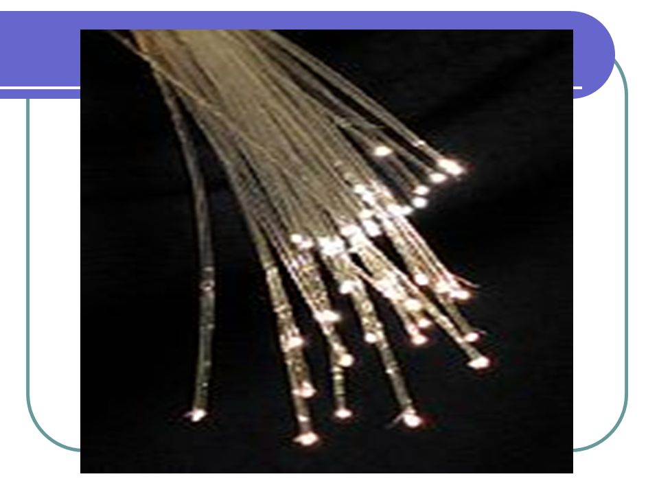
Applications of Total Internal Reflection
Periscopes (using a prism) Diamonds and bicycle reflectors Optical fibres – in telecommunications and by doctors
 Diamonds and bicycle reflectors. Optical fibres – in telecommunications and by doctors.")
55
PERISCOPE (diagram page 14)
")
56
Total internal reflection in a prism

57
Total internal reflection in a prism

58
Total internal reflection in a prism

60
Remember that rays are path-reversible
AIR GLASS A B

61
Example The refractive index of glass is 1.5
This value is for a ray of light travelling from air into glass So = = 1.5 = Or = =

62
Mirages Mirages are caused by the refraction of light in air due to temperature variations

63
SKY

64
Convex lens (converging)
LENSES Convex lens (converging)
")
65
Concave lens (diverging)
")
66
Ray diagrams for lenses
1. Ray incident parallel to principal axis is refracted out through focus 2. Ray incident through focus is reflected out parallel to axis 3. Ray incident through optic centre continues in straight line

67
Lens formulae u = distance from object to lens
v = distance from image to lens f = focal length

68
Magnification m = Or m =

69
Experiment to measure the Focal Length of a Concave Lens (page 29)
")
70
RAY BOX CROSS THREADS CONVEX LENS SCREEN (Diagram page 29)
")
71
Two Lenses in Contact Where F = focal length of combination
f1 and f2 are the focal lengths of the two lenses

72
Dispersion is the breaking up of white light into its constituent colours
In 1666 Newton at the age of 23, performed his famous prism experiment. He noticed and recorded that sunlight is white light that contains all the colors of the spectrum.

73
Spectrum of Visible Light
Y G B I V Color is an electromagnetic wave phenomenon. It is a sensation produced when light stimulates the retina of the eye, and the brain interprets this sensation as 'color'. Red is deviated the least and has the longest wavelength Violet is deviated the most and has the shortest wavelength

74
Uses of lenses Magnifying glass Spectacles Binoculars
Compound microscope Astronomical telescope

75
Magnifying glass/Simple Microscope
Is simply a convex lens, with the object placed inside the focus point Image is magnified, erect and virtual F

76
The Compound Microscope
Eyepiece Objective lens Fo Fe The microscope was invented about 1590 by Zacharias Jenssen of Holland.

77
The compound microscope
Consists of 2 convex lenses The first image is formed at the focal point of the eyepiece The final image is formed at infinity so we view it with a relaxed eye This is called ‘normal adjustment’ The image formed is inverted

78
The Astronomical Telescope
Objective lens Eyepiece Fe Fo Hans Lippershey was a Dutch lens grinder and maker of spectacles. He is usually credited with the invention of the first telescope about 1600 and he applied for a patent in About a year later, various lens grinders of northern Europe, were making telescopes. Records show that the telescope was further developed by Galileo and by others.

79
Same description as for compound microscope

Similar presentations


 Ltd. Final image at infinity Eye-ring Eye-ring 12.6 Refracting telescope.>")


:>")


 real image. (B) virtual image.>")
