Download presentation
Presentation is loading. Please wait.

1
Chapter 26 Geometrical Optics Snell’s Law Thin Lens Equation

2
1) Index of Refraction, n Speed of light is reduced in a medium Air1.000293 Water4/3 Glass1.5 Diamond2.4
 Index of Refraction, n Speed of light is reduced in a medium Air Water4/3 Glass1.5 Diamond2.4")
3
2) Snell’s Law a) Reflection and Transmission Transmitted ray light splits at an interface
 Snell’s Law a) Reflection and Transmission Transmitted ray light splits at an interface")
4
Transmitted ray

5
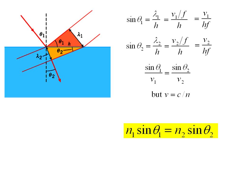
(b) Refraction: Transmitted ray is bent at interface toward normal if n increases
 Refraction: Transmitted ray is bent at interface toward normal if n increases")
6
away from normal if n decreases

7
toward normal if n increases c) Derivation of Snell’s Law
 Derivation of Snell’s Law")
9
Example: Rear-view mirror

10
Example: Apparent Depth

11
x d For small angles, d’

12
3) Total internal reflection a) The concept For small values of 1, light splits at an interface
 Total internal reflection a) The concept For small values of 1, light splits at an interface")
13
For larger values of 1, 2 > 90º and refraction is not possible Then all light is reflected internally Note: this is only possible if n 1 > n 2

14
b) Critical incident angle Snell’s law:
 Critical incident angle Snell’s law:")
15
Some critical angles Water-air: 49º Glass - air: 42º Diamond - water: 33º Diamond - air: 24º Why diamonds sparkle

16
c) Prisms (glass-air critical angle = 45º)
 Prisms (glass-air critical angle = 45º)")
17
Prisms in binoculars –Longer light path –Image erect

18
d) Fibre optics Low loss transmission of light, encoded signals.
 Fibre optics Low loss transmission of light, encoded signals.")
19
Fibre optic bundles, coherent bundles Imaging applications: endoscopy

21
4) Dispersion Index of refraction depends on wavelength
 Dispersion Index of refraction depends on wavelength")
22
Rainbow

23
Sun Dogs (parhelia)
")
24
5) Image Formation a) Seeing an object Diffuse reflection
 Image Formation a) Seeing an object Diffuse reflection")
25
b) Image formation with a pinhole Diffuse reflection Diffuse reflection screen
 Image formation with a pinhole Diffuse reflection Diffuse reflection screen")
26
Characteristics of pinhole imaging –Infinite depth of field (everything in focus) –Arbitrary magnification –Low light (increasing size produces blurring) Diffuse reflection screen Diffuse reflection
 –Arbitrary magnification –Low light (increasing size produces blurring) Diffuse reflection screen Diffuse reflection")
27
c) Ideal lens
 Ideal lens")
28
Characteristics of the ideal lens –All rays leaving a point on object meet at one point on image –Only one perfect object distance for selected image distance (limited depth of field -- better for smaller lens)
")
29
6) Thin lenses a) Converging - thicker in the middle
 Thin lenses a) Converging - thicker in the middle")
30
(i) Parallel coaxial rays converge at focus Reversible
 Parallel coaxial rays converge at focus Reversible")
31
(ii) Symmetric - rays leaving focal point emerge parallel (f’ = f)
 Symmetric - rays leaving focal point emerge parallel (f’ = f)")
32
(iii) Ray through centre undeviated
 Ray through centre undeviated")
33
Summary of ray tracing rules for converging lens

34
b) Diverging - thinner in the middle
 Diverging - thinner in the middle")
35
(i) parallel, coaxial rays diverge as if from focus Reversible
 parallel, coaxial rays diverge as if from focus Reversible")
36
(ii) symmetric - rays converging toward focus emerge parallel
 symmetric - rays converging toward focus emerge parallel")
37
(iii) ray through centre undeviated
 ray through centre undeviated")
38
Summary of ray-tracing rules for diverging lens

39
c) Real lenses: - usually spherical surfaces - approximate ideal lens for small angles (paraxial approximation)
 Real lenses: - usually spherical surfaces - approximate ideal lens for small angles (paraxial approximation)")
40
7) Image Formation with thin lenses (ray tracing) (a)Converging lens - real image Use 2 of 3 rays:
 Image Formation with thin lenses (ray tracing) (a)Converging lens - real image Use 2 of 3 rays:")
41
camera /CCD sensor

42
(b) Converging lens - virtual image
 Converging lens - virtual image")
43
(c) Diverging lens - virtual image
 Diverging lens - virtual image")
44
8) Thin Lens Equation a) The equation
 Thin Lens Equation a) The equation")
45
b) Sign Convention (left to right) (i)Focal Length: f > 0 converging f < 0 diverging (ii) Object distance d o > 0 left of lens (real; same side as incident light) d o < 0 right of lens (virtual; opposite incident light) (iii) Image distance d i > 0 right of lens (real; opposite incident light) d i < 0 left of lens (virtual; same side as incident light) (iv) Image size h i > 0 erect h i < 0 inverted
 Sign Convention (left to right) (i)Focal Length: f > 0 converging f < 0 diverging (ii) Object distance d o > 0 left of lens (real; same side as incident light) d o < 0 right of lens (virtual; opposite incident light) (iii) Image distance d i > 0 right of lens (real; opposite incident light) d i < 0 left of lens (virtual; same side as incident light) (iv) Image size h i > 0 erect h i < 0 inverted")
46
c) Lateral magnification Definition: From geometry (and sign convention):
 Lateral magnification Definition: From geometry (and sign convention):")
47
9) Compound Lenses Image of first lens is object for the second lens. Apply thin lens equation in sequentially.

49
Overall magnification is the product:

50
Example: Problem 26.66 Find final image and magnification.

51
10) Vision and corrective lenses a) Anatomy of the eye
 Vision and corrective lenses a) Anatomy of the eye")
52
120 x 10 6 rods - detect intensity: slow, mono, sensitive 6 x 10 6 cones - detect frequency: R - 610 nm, G - 560 nm, B - 430 nm

53
b) Optics - Accomodation: focal length changes with object distance - near point: nearest point that can be accomodated - normally < 25 cm - far point: furthest point that can be accomodated - normally ∞
 Optics - Accomodation: focal length changes with object distance - near point: nearest point that can be accomodated - normally < 25 cm - far point: furthest point that can be accomodated - normally ∞")
54
c) Myopia - far point < ∞ - near-sighted (far-blind) - correction: object at ∞ --> image at far point
 Myopia - far point < ∞ - near-sighted (far-blind) - correction: object at ∞ --> image at far point")
55
Correction: object at ∞ --> image at far point (ignoring the eye-lens distance)
")
56
d) Refractive Power For a far point of 50 cm, f = -50 cm, Lens prescription: -2
 Refractive Power For a far point of 50 cm, f = -50 cm, Lens prescription: -2")
57
e) hyperopia (hypermetropia) - near point > 25 cm - far-sighted (near-blind) - correction: object at 25 cm --> image at near point
 hyperopia (hypermetropia) - near point > 25 cm - far-sighted (near-blind) - correction: object at 25 cm --> image at near point")
58
Correction: object at 25 cm --> image at near point (ignoring the eye-lens distance) For near point of 40 cm, f = 66 cm Power = + 1.5 (reading glasses)
 For near point of 40 cm, f = 66 cm Power = (reading glasses)")
59
Examples: Problem 26.73 Age 40: f = 65.0 cm --> NP’ = 25.0cm Age 45: NP’ --> 29.0 cm (a) How much has NP (without glasses) changed? (b) What new f is needed? Problem 26.75 FP = 6.0 m corrected by contact lenses. (Find f) An object (h = 2.0 m) is d = 18.0 m away. (a)Find image distance with lenses. (b)Find image height with lenses.
 What new f is needed. Problem FP = 6.0 m corrected by contact lenses. (Find f) An object (h = 2.0 m) is d = 18.0 m away. (a)Find image distance with lenses. (b)Find image height with lenses..")
60
11) Angular Magnification a) Angular size
 Angular Magnification a) Angular size")
61
b) Angular magnification
 Angular magnification")
62
12) Magnifier With magnifier: (Magnifier allows object to be close to the eye)
 Magnifier With magnifier: (Magnifier allows object to be close to the eye)")
63
Without magnifier: Highest magnification (d i = -N): Lowest magnification (d i = -∞): (tense eye) (relaxed eye) (Magnification quoted with N = 25 cm, for relaxed eye)
: Lowest magnification (d i = -∞): (tense eye) (relaxed eye) (Magnification quoted with N = 25 cm, for relaxed eye)")
64
Example: Problem 26.82 Farsighted person has corrective lenses with f = 45.4 cm. Maximum magnification of a magnifier is 7.50 (normal vision). What is the maximum magnification of the magnifier for the farsighted person without lenses?
. What is the maximum magnification of the magnifier for the farsighted person without lenses .")
65
13) Compound Microscope Simple magnifier: M = N/f –to increase M, decrease f –practical limits to decreasing f (and therefore size): small lens difficult to manufacture and use increases aberrations Microscope introduces an additional lens to form a larger intermediate image, which can be viewed with a magnifier
 Compound Microscope Simple magnifier: M = N/f –to increase M, decrease f –practical limits to decreasing f (and therefore size): small lens difficult to manufacture and use increases aberrations Microscope introduces an additional lens to form a larger intermediate image, which can be viewed with a magnifier")
66
L Magnification: For image at ∞, d i2 = f e For max M, d o1 f o For d i2 = ∞, d i1 + f e = L

67
Example: Problem 26.88 Microscope with f o = 3.50 cm, f e = 6.50 cm, and L = 26.0 cm. (a) Find M for N = 35.0 cm. (b) Find d o1 (if first image at F e ) (c) Find lateral magnification of the objective.
 Find M for N = 35.0 cm. (b) Find d o1 (if first image at F e ) (c) Find lateral magnification of the objective..")
68
14) The Astronomical Telescope Magnifier requires d o ∞ for stars Introduce objective to form nearby image, then use magnifier on the image
 The Astronomical Telescope Magnifier requires d o ∞ for stars Introduce objective to form nearby image, then use magnifier on the image")
69
Magnification: Long telescope, small eyepiece

70
Example: Problem 26.94 Yerkes Observatory: f o = 19.4 m, f e = 10.0 cm. (a) Find angular magnification. (b) If h o = 1500 m (crater), find h i, given d o = 3.77 x 10 8 m (c) How close does the crater appear to be.
 Find angular magnification. (b) If h o = 1500 m (crater), find h i, given d o = 3.77 x 10 8 m (c) How close does the crater appear to be..")
71
Galilean Telescope (Opera glasses)
")
72
Reflecting Telescope

Similar presentations


 Ltd. Final image at infinity Eye-ring Eye-ring 12.6 Refracting telescope.>")


:>")


 Optics –Lenses –Eye.>")