Download presentation
Presentation is loading. Please wait.

1
N34208

2
Ground Training Notes For Cessna Cardinal RG

3
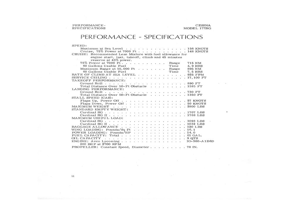
Performance Specifications
Good Speeds, expect 140 knot cruise Service Ceiling 17,100 feet Good short field performance 890 feet TO roll, 730 Landing Roll Stall speed Vso 50 Knots Useful Load just under 1000 pounds Small baggage allowance 120 pounds Low wing Loading 16.1 pounds/square foot

5
General Description Engine Lycoming IO-360-A1B6D (note D for dual magneto single drive) I – Fuel Injected 200HP at 2700 RPM 4 cylinders Propeller McCauley Constant Speed, 78 inch diameter Fuel 100LL 61 gallons total, 60 gallons usable Oil Capacity 9 quarts total, 8 sump

6
Important Limitations - POH Section 2
Maneuvering Speed 2800# KIAS, # KIAS (note major changes for weight) Flap Extension Speeds , Vfe 10 degrees 130 KIAS degrees 95 KIAS Landing Gear Operating/Extension Speeds, Vle 125 KIAS Maximum Vent Window Open Speed 105 KIAS Never Exceed Speed 174 KIAS Power Plant yellow arc 1400 to 1750 below 10 inches manifold Weight Limit 2800#, Center of Gravity shift with gear retraction #-inches Normal Category Only no flap NO SPINS Fuel Selector must be on BOTH for Landing Placards also shown in POH
 Flap Extension Speeds , Vfe 10 degrees 130 KIAS degrees 95 KIAS. Landing Gear Operating/Extension Speeds, Vle 125 KIAS. Maximum Vent Window Open Speed 105 KIAS. Never Exceed Speed 174 KIAS. Power Plant yellow arc 1400 to 1750 below 10 inches manifold. Weight Limit 2800#, Center of Gravity shift with gear retraction #-inches. Normal Category Only no flap. NO SPINS. Fuel Selector must be on BOTH for Landing. Placards also shown in POH.")
7
Aircraft Systems and Descriptions
POH Section 7

8
Airframe Cantilever Wing structure Wet Wing Tanks Stabilator Tail
Smooth Flaps and Ailerons Slots in Stabilator Tail to reduce stall speed of Stabilator

9
Instrument Panel

10
Instrument Panel (2)
")
11
Ground Control Best to use the Tow Bar for all ground Handling
NEVER PUSH On Stabilator Turn limits on tow bar 39 degrees right and left If necessary, push on main gear legs Minimum Turning radius using differential braking, approximately 31 feet

12
Operation of Flaps Pre-Select Flap Control
Detents for 10 degrees and 20 degrees Must move Flap Lever slightly right to pass 10 and 20 degree detents One finger can move flaps up after short field landing if maximum effort required

13
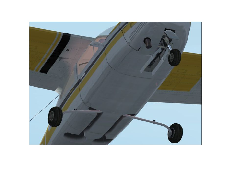
Landing Gear System Gear and Downlocks Hydraulically Actuated (5606 hydraulic fluid, red) Two Cylinders, one for both mains, one for nose gear Hydraulic Pressure comes from hydraulic power pack behind baggage compartment bulkhead

14
Landing Gear System (2) Landing Gear System Hydraulic Pressure serves to hold gear up, no up locks on main gear Power pack Operation controlled by pressure switch, 1500psi off, 1000psi on Landing gear Lever directs hydraulic pressure Lever must be pulled out slightly to change position, requires two fingers Position Indicator Lights for UP and DOWN If a bulb burns out, use other indicator, be very cautious if changing bulb in flight! Landing Gear Retraction or Extension takes just under 15 seconds

15
Landing Gear System (3) Safety Switch to prevent landing gear retraction on the Ground on nose gear disables any operation of the hydraulic pump Emergency Hand Pump provided in case of Electrical Pump Failure to Extend Gear Landing Gear does have Aural Warning unit that provides an intermittent tone thru the cabin speaker if the throttle is below 12 inches manifold pressure If all Hydraulic Fluid is lost, there is no way to extend the Landing Gear

18
Cabin Doors Doors are operated by a three position handle OPEN, CLOSE, LOCK Door Opening in Flight is not Serious and there is no need to Land Doors can be Closed in Flight with Procedure in POH DOORS ARE VERY LARGE and OPENING DOWNWIND CAN CAUSE HEAVY STRUCTURAL DAMAGE!

19
Engine and Engine Instruments
4 Cylinder 200HP Fuel Injected Lycoming with belt drive alternator dual magneto and prop governor Throttle and Friction knob Vernier Mixture Control CHT Gauge, ideally kept below 380 degrees f by use of Cowl Flaps Manifold Pressure Gauge, Normal range 15 to 25 inchs Fuel Flow / Fuel Pressure Gauge Normal range 6 to 13 GPH, 19 GPH redline

20
Engine and Engine Instruments (2)
EGT gauge used for leaning Engine oil, maintain 6 quarts minimum Automatic Alternate Air Door will open if needed 5% loss of power Cowl Flap Control to adjust engine cooling by trailing a lower cowling edge open

21
Propeller Constant Speed with Prop Governor to maintain speed
Governor is a pump which boosts the engine oil to higher pressure Governor also is set by prop control for a speed and senses engine speed to adjust oil pressure that is sent to the prop to adjust blade angle Oil pressure on the piston in the propeller hub twists the blades to higher pitch (lower rpm) Centrifugal force on counterweights plus an internal spring returns the pitch to low when oil pressure is removed from the piston If power is insufficient to maintain set RPM, then RPM will drop Special WARNING about Prop Governor Service
 Centrifugal force on counterweights plus an internal spring returns the pitch to low when oil pressure is removed from the piston. If power is insufficient to maintain set RPM, then RPM will drop. Special WARNING about Prop Governor Service.")
22
Fuel System

23
Fuel System (2) Two Integral fuel tanks formed by sealing off part of the wing Two Fuel Reservoir Tanks (Header Tanks) with integral drains connected to lever on floor Fuel Valve has Left, Right, Both and Off Electric Auxiliary Pump used mostly for Priming Fuel Servo hooks to throttle and mixture control and senses mass air flow Fuel Servo sends a specific fuel pressure to the diverter manifold which distributes to each injector and to the Fuel Pressure gauge calibrated for Fuel Flow Vent lines for Fuel Tanks on opposite wing Line of holes in filler neck allows easy fueling to 22 gallons each side for larger loads Fuel Selector must be in BOTH position for Takeoff and Landing Use the Auxiliary Electric Fuel Pump in the event of engine driven pump failure
 with integral drains connected to lever on floor. Fuel Valve has Left, Right, Both and Off. Electric Auxiliary Pump used mostly for Priming. Fuel Servo hooks to throttle and mixture control and senses mass air flow. Fuel Servo sends a specific fuel pressure to the diverter manifold which distributes to each injector and to the Fuel Pressure gauge calibrated for Fuel Flow. Vent lines for Fuel Tanks on opposite wing. Line of holes in filler neck allows easy fueling to 22 gallons each side for larger loads. Fuel Selector must be in BOTH position for Takeoff and Landing. Use the Auxiliary Electric Fuel Pump in the event of engine driven pump failure.")
24
Caution with vent lines interfering with Ailerons

25
Hydraulic System

26
Hydraulic System (2) Electrical Hydraulic Pump
Separate 30 amp Circuit Breaker Push/Pull type Pump turned on by Pressure Switch Proper Application of Pressure direction selected by the Gear Selector Handle, a simple valve When the gear reaches an end point, up or down, the Reed Switches close to illuminate the bulb either up or down CAUTION, shorting the bulb socket will damage the Reed Switches Permanently if power applied

27
Hydraulic System (3) Emergency Hand pump Functions to pump gear down, located between the front seats Normal Operation time is 12 to 13 seconds for extension or retraction

28
Electrical System 14 Volt 60 Amp Alternator
Split Buss Contactor to Separate Electronics Bus, Also hooks to Avionics Master Split Master Switch Ammeter indicates Charging Rate of Battery Only Over Voltage Warning Light will illuminate if the Field Current is Removed Turn Master Switch Off and Back on to Reset Ground Service Plug – Cannot be used to run Radios on the Ground Can be used to Charge a Dead Battery if Master is turned on after Connection

30
Vacuum System and Instruments
Dry Vacuum pump – Can fail suddenly AI and HI both Vacuum Driven Normal Suction 4.6 to 5.4 inches Mercury

31
Vacuum System and Instruments (2)
N34208 Equipped with SVS Backup Vacuum System and Warning Light Vacuum from engine Manifold riser is used to provide Suction in the event of Pump Failure Must NOT have throttle full in to work, need to reduce Manifold Pressure according to Placard, approximately 2 inches

32
Vacuum System and Instruments (3)
To activate Pull Handle

33
Autopilot Wing leveler Heading Hold Nav Trak
Uses Heading Indicator and Turn Coordinator as Feedback

34
Weight & Balance & Equipment List

35
Normal Operations

36
Key Speeds 62 KIAS - Short Field T.O. speed at 50 feet with 10 degrees flap 82 KIAS - Vy best rate SL. 90 – 100 KIAS Normal Climb 63 KIAS Short Field Approach with 30 Degrees Flap (plus allowance for gust) Maximum Demonstrated Crosswind 16 Knots
 Maximum Demonstrated Crosswind 16 Knots.")
37
Normal Operations (2) Starting Engine Cold and Hot, Dangers of Fire
Power Check Wing Flap Settings Retraction of Gear After Takeoff Crosswind T.O. Enroute Climb and normal power, fuel flow and speeds, engine temperatures, cowl flaps Cruise, setup, leaning, power setting, cowl flaps Descents MP, cooling Before Landing CGUMP Final Fence Check Go Around

39
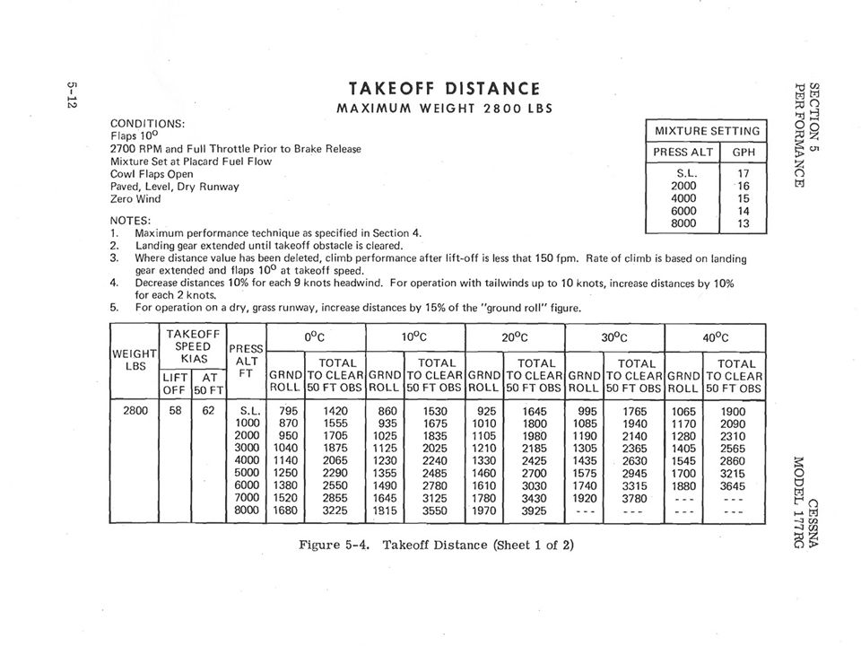
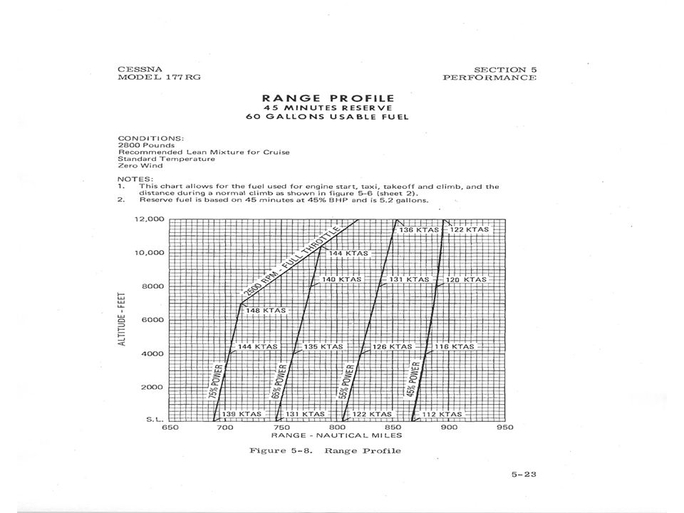
Performance Charts Takeoff distance chart page 5-12
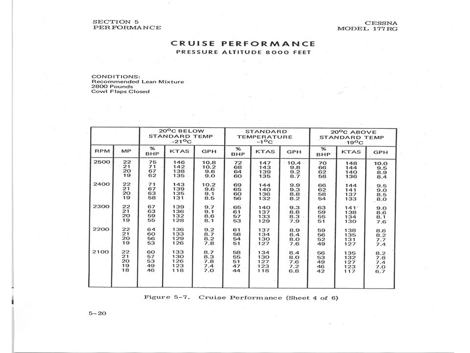
Time Fuel Distance to Climb chart page 5-16 Cruise Performance Chart PA 8000 page 5-20 Range Profile chart page 5-23 Landing Distance chart page 5-25

45
Emergency Procedures

Similar presentations


>")


