Download presentation
Presentation is loading. Please wait.

1
1 Application and Analysis of Helical Piers in Frozen Ground He Liu, Ph.D., P.E. Daniel Schubert, P.E. Hannele Zubeck, Ph.D., P.E. Sean Baginski

3
3 Applications and Advantages Helical piers have been used for above ground water and wastewater transmission lines Helical piers have a great potential for use in remote villages and facilities Advantages: not only because they provide stable foundations but also because of their light weight and fast installation time.

9
Helical Pier for Utilidor in St. Michael

10
Helical Pier Used for Boardwalk Bridge in Tuntutuliak

11
11 Helical piers are widely used in soft soils, however, no data nor design procedures exist for frozen ground applications. Problems related to frozen ground include the risk that the piers will fail during the installation and long-term deformation due to frozen ground creep.

14
14 Study Objectives Helical pile stress distribution during installation Helical pile stress distributions under axial load Pile displacement and soil stress under axial loading Long term pile displacement (creep) Results will compare with tests in CRERL
 Results will compare with tests in CRERL")
15
15 Method of Analyses To investigate the behavior of helical pier foundations in frozen ground, and To develop design and installation guidelines, Finite Element Analysis (FEA) models are developed in this study. The scope of work includes developing FEA models to simulate the force-deformation relationships in the pier and the stress-strain relationships in the surrounding frozen soil.

16
16

17
17 Installation Failure Model FEA model: shell elements Torque = 90 kip-in Restraint: At pipe bottom and leading edge

18
18 Y = 50 ksi E = 29,000 ksi E T = 1450 ksi This yield criterion allows for both elastic and plastic deformation of the steel. Bilinear Yield Criteria:

19
Von Mises Stress on Helix Stress, ksi 0.0 1 2 4 8 16 32 64 Torque = 90 kip-in

20
von Mises Stress on Helix Stress, ksi 8.1 16.1 24.2 32.2 40.3 48.3 56.4 64.4 72.5 Torque = 90 kip-in Yield occurs near the corner Consistent with real failures FEA can provide the accurate maximum torque.

21
21

22
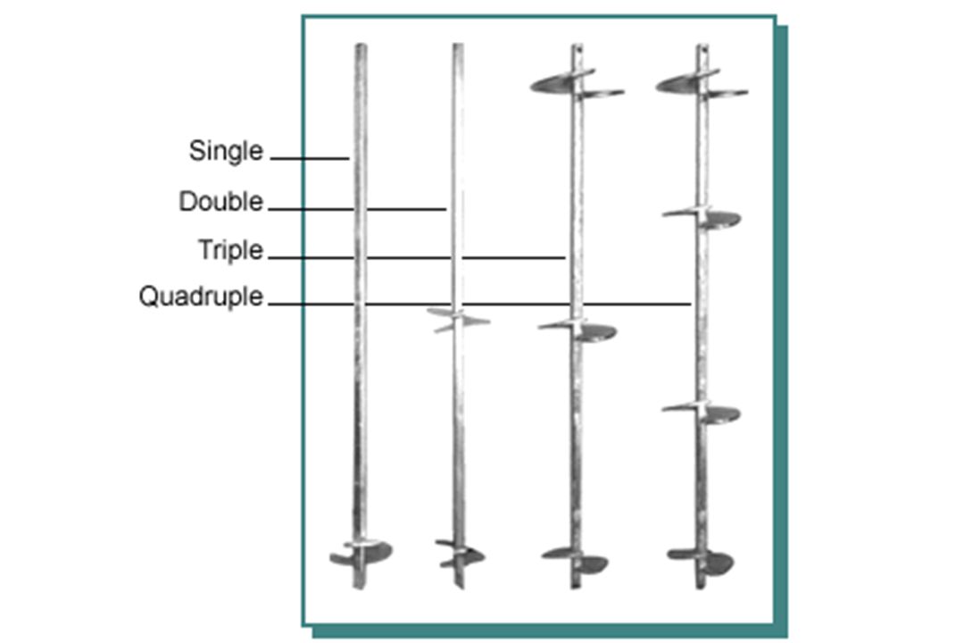
22 Soil-Helix Model 2 helix configuration Diameter = 50” Depth = 180” Helix – 3-1/2 shaft –10” diameter –1/2” steel plate –30” spacing

23
23 Drucker-Prager Circular Cone Yield Surface

24
24

25
25

26
Vertical Displacement in Soil 2 helix, Axial Load = 20 kips - Shallow Model

27
27 Vertical Stress in Soil 2 helix, Axial Load = 20 kips - Shallow Model

28
Axial Load = 20 kips Deep Model

29
29 Vertical Stress in Soil, Axial Load=20 kips Deep Model

30
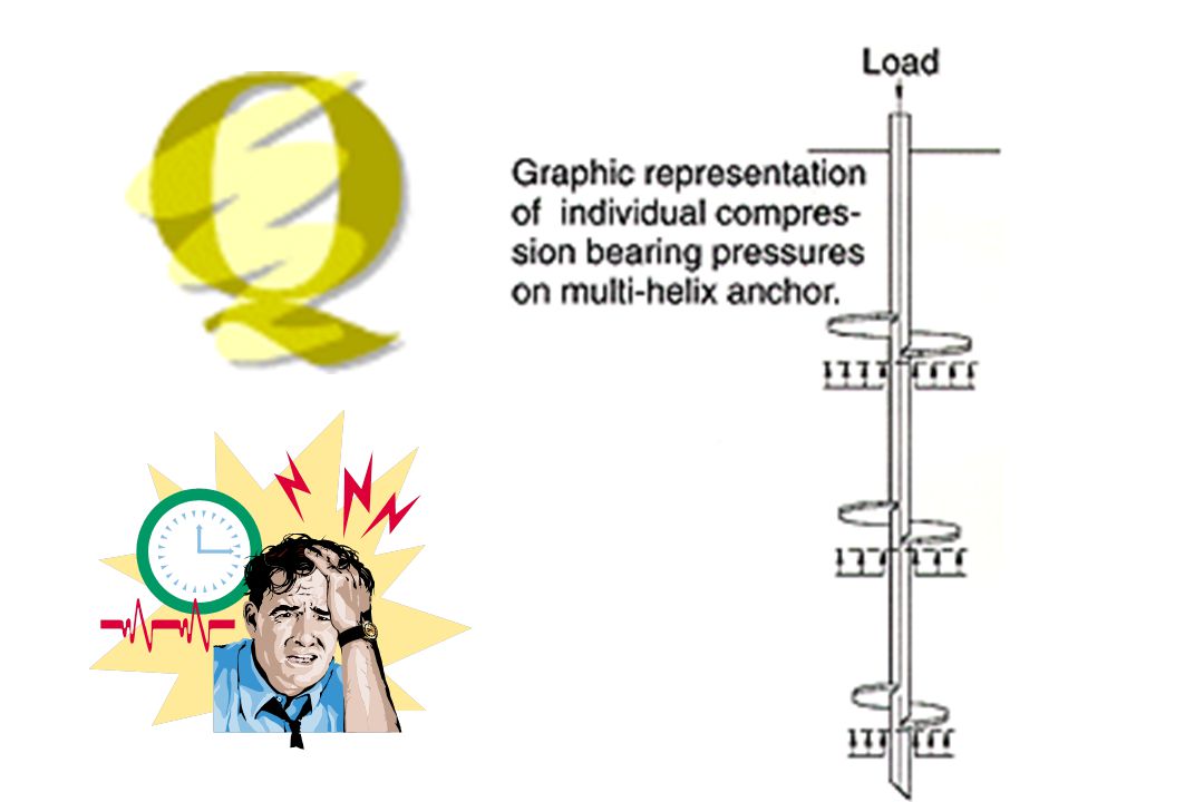
30 In case of: two helix plates, three times diameter apart each other Soil reaction pressure below the bottom plate is 3-4 times larger than that of the top plate The bottom plate takes >70% of the total load The reasons are: - Steel shaft is very stiff between two plates, almost no shortening - Soil deformation between two plates is mainly controlled by the steel deformation

31
31

32
32 Sub Model –from the Shallow Model Submodel from Large Model Soil - 15” diameter Depth = 10” Helix –3-1/2” shaft –10” diameter –1/2” thickness

33
Vertical Stress in Soil Below Helix Stress, psi -19.5 -17.0 -14.5 -11.9 -9.4 -6.9 -4.4 -1.9 0.0 Axial Load=20 kips - Sub Model

34
34 Vertical Soil Stress - Sub Model Axial Load=20 kips

35
35 Helical Pier Stress – Sub Model von Mises stress in Helix, Axial Load =20 kips Biaxial-bending behavior Information for welding

36
36

37
Creep Equation - for the Shallow Model where: n = 3 e = equivalent stress cu = 38 kPa at -0.15 C.

38
38 Creep Model Results – Shallow Model Displacement vs. Time 2 Year at –0.15 o C Secondary Creep Axial Load = 7 kips Soil – frozen silt = 31 o c = 5 psi = 130 pcf Nonlinear analysis Time consuming

39
39 Conclusions Helical piers have a great potential for use in remote villages and facilities. The FEA model results will increase understanding of helical piers in various soil conditions as well as provide insight into design and installation considerations. Soil stress is not uniformly distributed under helix. Further refinements in design procedures are necessary. Creep analysis indicates linear secondary settlement. It will provide valuable information for use the piers in frozen ground.

40
40

Similar presentations