Download presentation
Presentation is loading. Please wait.

2
Conceptual & Thermodynamic Description of Expansion in I.C. Engine P M V Subbarao Professor Mechanical Engineering Department The Actual & Useful Extent of Work Output….

3
The Otto’s Suggestion for Expansion Process

4
Actual Scope for Expansion Process

5
The Diesel’s Suggestion for Expansion Process

6
Actual Scope for Expansion Process

7
The Influence of Simple Mechanism A I R Combustion Products Ignition Intake Stroke FUEL Fuel/Air Mixture Compression Stroke Power Stroke Exhaust Stroke Actual Cycle A I R Combustion Products Fuel injected at TC Intake Stroke Air Compression Stroke Power Stroke Exhaust Stroke Actual Cycle

8
Expansion in A Conventional Engine

9
Work Delivered during Expansion : Control Mass

10
The Pseudo Cooling Process

11
Exhaust blowdown Late in power cycle exhaust valve is opened Pressure differential pushes hot exhaust gas out of cylinder and through exhaust system. When piston is at BDC Exhaust gas carries away high amount of enthalpy, which lowers cycle thermal efficiency. The mass blow down process, which occurs between EVO and BDC (180 CA), is to be thermodynamically designed to enhance the predictive capability of the cyclic integral. An empirical correlation for the blow down pressure is obtained as in the following form:
, is to be thermodynamically designed to enhance the predictive capability of the cyclic integral. An empirical correlation for the blow down pressure is obtained as in the following form:.")
12
Nature of Blowdown After EVO, the mass in cylinder decreases sharply as gas blowdown occurs due to the significant pressure difference across the exhaust valve. In the most cases, 20% -- 50% of the exhaust gas exits the exhaust valve during the blowdown process. During the exhaust stroke, the piston moves towards TDC, which further pushes the mass of gases in cylinder to leave the engine. At 720 o CA, the mass of gases residing in the clearance volume, which is termed as the residual gas, will be mixed with the fresh intake charge in the subsequent cycle

13
Empirical Relations for Pressure during blowdown where and m =0.45 is the shape factor determined by experimental correlation.

14
Intake Conditions The residual mass fraction (f ), a parameter which is crucial in the determination of the charge air/gas temperature at IVC (Ti). This is estimated from the previous cycle. Hence, the residual mass fraction can be estimated by

15
Pressure/Volume diagram of 4-stroke cycle at 4000 rpm

17
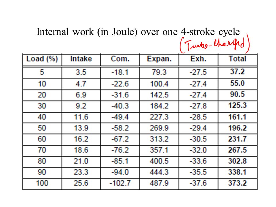
Internal work (in Joule) over one 4-stroke cycle
 over one 4-stroke cycle")
18
The Problem The problem is due to the fact, that the single reciprocating device has a compression stroke which is equal to the expansion stroke. On one hand, you need a high expansion stroke in order to convert the maximum of thermal energy into work. On the other hand, you need a rather low compression stroke, in order to limit the thermal and mechanical stresses, as well as the non controlled ignition for gasoline cycles. This leads to the situation, that the four-stroke cycles should only be run with a rather small load pressure range (absolute load pressure = 1.2... 2 bar), with throttling for low loads. “Don’t throttle the engine down, load it up!”
, with throttling for low loads. Don’t throttle the engine down, load it up! .")
19
The Unreasonable Bias A I R Combustion Products Ignition Intake Stroke FUEL Fuel/Air Mixture Compression Stroke Power Stroke Exhaust Stroke

20
A General Physician to A Team of Specialists One device designed to increase and control the breathing The turbo- or supercharging device (load pressure 1...5 bar) One device where the primary task is to burn this air... The high pressure cylinder. One device to complete the conversion of the thermal energy into mechanical work. The low pressure cylinder.

21
In 2000, a new engine is born... Three cylinder 5-Stroke engine

22
The Five Stroke Cycle The five-stroke cycle consists in the following steps: 1. Admission in the high pressure (HP) cylinder 2. Compression, followed by the ignition 3. First expansion of the burned gases 4. Second expansion of the burned gases 5. Exhausting of the burned gases.
 cylinder 2. Compression, followed by the ignition 3. First expansion of the burned gases 4. Second expansion of the burned gases 5. Exhausting of the burned gases..")
Similar presentations


 Patel Vidhi A.>")


 to the 'top dead center' (TDC) or the other way round,>")


