Download presentation
Presentation is loading. Please wait.

1
The Camera 15-463: Computational Photography Alexei Efros, CMU, Fall 2006

2
How do we see the world? Let’s design a camera Idea 1: put a piece of film in front of an object Do we get a reasonable image? Slide by Steve Seitz

3
Pinhole camera Add a barrier to block off most of the rays This reduces blurring The opening known as the aperture How does this transform the image? Slide by Steve Seitz

4
Pinhole camera model Pinhole model: Captures pencil of rays – all rays through a single point The point is called Center of Projection (COP) The image is formed on the Image Plane Effective focal length f is distance from COP to Image Plane Slide by Steve Seitz
 The image is formed on the Image Plane Effective focal length f is distance from COP to Image Plane Slide by Steve Seitz")
5
Figures © Stephen E. Palmer, 2002 Dimensionality Reduction Machine (3D to 2D) 3D world2D image What have we lost? Angles Distances (lengths)
 3D world2D image What have we lost. Angles Distances (lengths).")
6
Funny things happen…

7
Parallel lines aren’t… Figure by David Forsyth

8
Distances can’t be trusted... Figure by David Forsyth B’ C’ A’

9
…but humans adopt! http://www.michaelbach.de/ot/sze_muelue/index.html Müller-Lyer Illusion We don’t make measurements in the image plane

10
Building a real camera

11
Camera Obscura The first camera Known to Aristotle Depth of the room is the effective focal length Camera Obscura, Gemma Frisius, 1558

12
Home-made pinhole camera http://www.debevec.org/Pinhole/ Why so blurry?

13
Shrinking the aperture Why not make the aperture as small as possible? Less light gets through Diffraction effects… Less light gets through Slide by Steve Seitz

14
Shrinking the aperture

15
The reason for lenses Slide by Steve Seitz

16
Ideal Lens: Same projection as pinhole but gathers more light! i o Lens Formula: f is the focal length of the lens – determines the lens’s ability to bend (refract) light f different from the effective focal length f discussed before! P P’ f Image Formation using Lenses Slide by Shree Nayar
 light f different from the effective focal length f discussed before. P P’ f Image Formation using Lenses Slide by Shree Nayar.")
17
Focus

18
Focus and Defocus A lens focuses light onto the film There is a specific distance at which objects are “in focus” –other points project to a “circle of confusion” in the image How can we change focus distance? “circle of confusion” Slide by Steve Seitz

19
Varying Focus Ren Ng

20
Depth Of Field

21
Depth of Field http://www.cambridgeincolour.com/tutorials/depth-of-field.htm

22
Aperture controls Depth of Field Changing the aperture size affects depth of field A smaller aperture increases the range in which the object is approximately in focus But small aperture reduces amount of light – need to increase exposure

23
Varying the aperture Large apeture = small DOFSmall apeture = large DOF

24
Nice Depth of Field effect

25
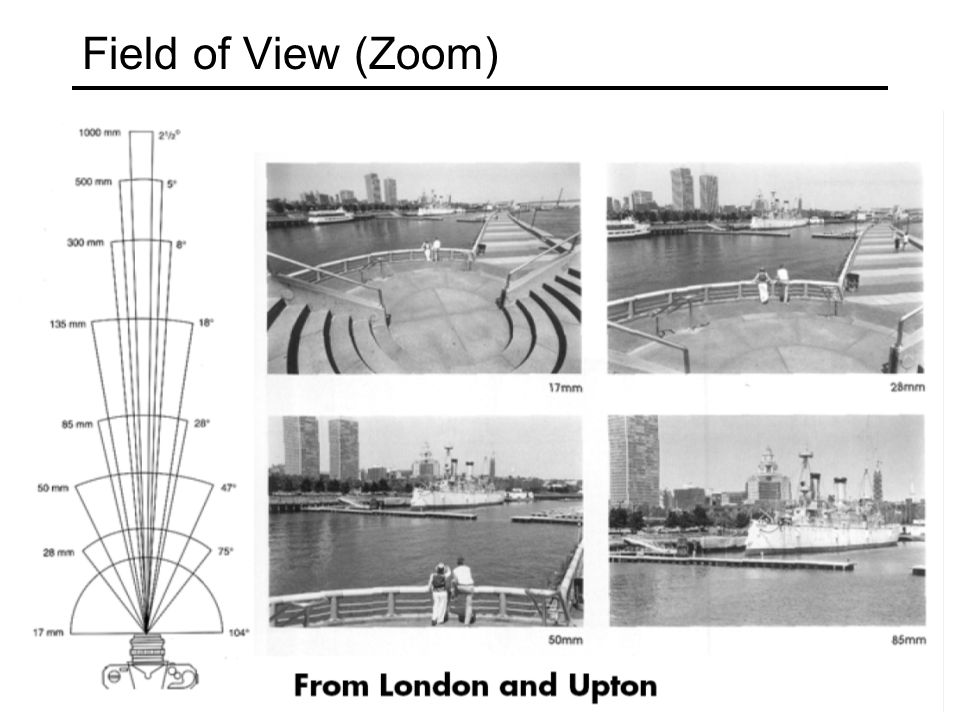
Field of View (Zoom)
")
28
f FOV depends of Focal Length Smaller FOV = larger Focal Length

29
From Zisserman & Hartley

30
Field of View / Focal Length Large FOV, small f Camera close to car Small FOV, large f Camera far from the car

31
Fun with Focal Length (Jim Sherwood) http://www.hash.com/users/jsherwood/tutes/focal/Zoomin.mov
")
32
Large Focal Length compresses depth © 1995-2005 Michael Reichmann 400 mm 200 mm 100 mm 50 mm 28 mm 17 mm

33
Lens Flaws

34
Lens Flaws: Chromatic Aberration Dispersion: wavelength-dependent refractive index (enables prism to spread white light beam into rainbow) Modifies ray-bending and lens focal length: f( ) color fringes near edges of image Corrections: add ‘doublet’ lens of flint glass, etc.
 Modifies ray-bending and lens focal length: f( ) color fringes near edges of image Corrections: add ‘doublet’ lens of flint glass, etc.")
35
Chromatic Aberration Near Lens Center Near Lens Outer Edge

36
Radial Distortion (e.g. ‘Barrel’ and ‘pin-cushion’) straight lines curve around the image center
 straight lines curve around the image center")
37
Radial Distortion Radial distortion of the image Caused by imperfect lenses Deviations are most noticeable for rays that pass through the edge of the lens No distortionPin cushionBarrel

38
Radial Distortion

39
Modeling Projections

40
Modeling projection The coordinate system We will use the pin-hole model as an approximation Put the optical center (Center Of Projection) at the origin Put the image plane (Projection Plane) in front of the COP –Why? The camera looks down the negative z axis –we need this if we want right-handed-coordinates – Slide by Steve Seitz

41
Modeling projection Projection equations Compute intersection with PP of ray from (x,y,z) to COP Derived using similar triangles (on board) We get the projection by throwing out the last coordinate: Slide by Steve Seitz
 to COP Derived using similar triangles (on board) We get the projection by throwing out the last coordinate: Slide by Steve Seitz")
42
Homogeneous coordinates Is this a linear transformation? Trick: add one more coordinate: homogeneous image coordinates homogeneous scene coordinates Converting from homogeneous coordinates no—division by z is nonlinear Slide by Steve Seitz

43
Perspective Projection Projection is a matrix multiply using homogeneous coordinates: divide by third coordinate This is known as perspective projection The matrix is the projection matrix Can also formulate as a 4x4 divide by fourth coordinate Slide by Steve Seitz

44
Orthographic Projection Special case of perspective projection Distance from the COP to the PP is infinite Also called “parallel projection” What’s the projection matrix? Image World Slide by Steve Seitz

45
Spherical Projection What if PP is spherical with center at COP? In spherical coordinates, projection is trivial: d Note: doesn’t depend on focal length d!

46
Programming Assignment #1 Out tonight, due Sept. 11, 11:59pm Easy stuff to get you started with Matlab Matlab Tutorial Bells and Whistles Deal with borders Play with distance functions Try stitching something else (areal maps, etc)
.")
Similar presentations

 Ifeoma Nwogu Lecture 4 – Image formation(part I)>")

>")


 Project 1 additional test sequences online Talk today on “Lightfield photography” by Ren.>")


 vote on best artifacts in next week’s class Project 2 groups.>")


 with a lot of slides stolen from.>")