Download presentation
Presentation is loading. Please wait.

1
ROTARY INSTRUMENTS IN CONSERVATIVE DENTISTRY
Dr . VIJAY KUMAR SHAKYA Dept of Conservative Dentistry and Endodontics

2
INTRODUCTION The term SPEED in dentistry has greater importance in all the treatment procedures . SPEED refers to revolution per minute. certain speedy devices like handpiece ultrasonic , sonic instruments plays greater role in dentistry .

3
What is an handpiece ? A hand piece is a - device for holding rotating instruments, transmitting power to them and for positioning them intra orally.

4
Uses to cut tooth structure for various types of preparations. to remove old metal restorations to polish teeth and finish various types of restorative materials. The hand piece may also be used in oral surgery and for implant procedure.

5
Most development of methods for preparing teeth has occurred within the last 100 years .effective equipment for removal and preparation of enamel has been available since speeds of 10,000 rpm were first used along with newly marketed carbide burs and diamond instruments. Since 1953 continued improvements have results in equipment that is efficient as well as sterlizable.

6
HISTORY / EVOULTION 1868 – Dr.Jonathan Taft in his text book of operative dentistry. Cutting procedures on tooth enamel and dentin were carried out using thick, bulky chisels and excavators. The first rotary instruments used for cutting tooth tissue were actually drill or bur head that could be twisted in the fingers, for a cutting action. He described them as “bur drills”.

7
One of the refinements of these bur drills was scrantons drill
One of the refinements of these bur drills was scrantons drill. This could be rotated in either direction to achieve its cutting action. The next modification was drill ring.

8
1871 – Morrison modified and adapted the dental foot engine from the singer sewing machine. For the first time, cutting procedures were carried out with a power source. 1883 – electric dental engine linked to the hand piece by a flexible cable arm was introduced. 1910 – belt driven hand piece was introduced 1950 – ball bearing hand piece was introduced

9
1953 – nelson introduced, first fluid turbine type hand piece with speed of 50,000 rpm.
1954 – air driven hand piece were developed with possible speed of 150,000 rpm. 1957 – rotational speed was increased to 300,000 rpm 1960’s – introduction of air bearing hand piece with speed of 500,000 rpm. 1963 – ultrasonic method of tooth tissue removal with vibrating frequency ranging from 15, ,000 cycles / second.

13
How do we classify handpiece?
Dental hand pieces classified according to driving mechanism Gear driven hand piece Water driven hand piece Belt driven hand piece Air driven hand piece

14
Each is designed for a specific range of functions
Depending upon angulations Straight Contra angled Right angled Each is designed for a specific range of functions

15
Straight hand piece the straight hand piece may also be used with a straight shank. Rotary instrument on anterior teeth or where a direct approach to teeth is possible.

16
Contra angled hand piece is designed to provide the operator with greater accessibility to the oral cavity during operative dentistry. Right angle hand piece in which the head of the hand piece forms a 90o angle to the shank. The most popular right angle hand piece is the prophy angle.

17
DEPENDING ON SPEED Speed is defined as the number of revolution per minute (RPM) or the number of times a rotating instrument, such as a bur, will make a full turn during a minute. The higher the rpm, the faster the speed of hand piece. Low or slow speed - below 12,000 rpm Medium or intermediate speed - 12,000 to 200,000 rpm High or ultra speeds - above 200,00 rpm
 or the number of times a rotating instrument, such as a bur, will make a full turn during a minute. The higher the rpm, the faster the speed of hand piece. Low or slow speed - below 12,000 rpm. Medium or intermediate speed - 12,000 to 200,000 rpm. High or ultra speeds - above 200,00 rpm.")
18
AIROTOR (or air turbine) speed 250,000 – 500,000 rpm gives the highest speeds but with rather less torque than low speed hand piece. The high speeds are achieved by a small air driven rotor or turbine mounted in bearings in the head of a airotor hand piece. The hand piece always contains a system which directs water spray at the cutting head of the bur and often also contains a fiber – optic light.

19
LOW SPEED HAND PIECE Speed ranges from 10,000 to 30,000 rotations per minute (rpm) Low speed hand piece Straight Contra angle The speed of these hand piece is less but the torque is greater. Low speed hand pieces can be rotated clockwise or anticlockwise, where as airotor only rotates clockwise.

20
SELECTION OF LOW SPEED HAND PIECE

21
1:1 Ratio contra angle handpiece used for most procedures.
Latch grip burs are used. Commonly identified with the blue color on the shank of the handpiece and a blue dot on the head. Speed range rpm 1:4 Speed increasing handpiece. Commonly identified with the red band. Speed rpm

22
7:1 Ratio speed reducing handpiece used for drilling pin holes and other procedures where slow speed is indicated.Commonly identified with the green band.Speed range rpm

25
USES Low or slow speed cleaning teeth, occasionally caries excavation finishing and polishing procedures. ADVANTAGES – At low speeds, tactile sensation is better and there is generally less chances for over heating cut surfaces.

26
DISADVANTAGES Cutting is ineffective, more time consuming and produces vibrations of low frequency and high amplitude. Heat and vibrations are the main sources of patient discomfort.

27
HIGH SPEED HANDPIECE Operates at speeds up to 450,000 rpM Tooth preparation Removing old restoration. with high speed cutting instruments removal of tooth structure is faster with less pressure, vibration and heat production. Patients are generally less apprehensive because annoying vibrations and operating time are decreased Variable control to regulate the speed makes the hand piece more versatile. This allows the operator to easily obtain the optimal speed for the size and type of rotating instrument at any stage of a specific operation.

28
PARTS OF THE DENTAL HAND PIECE
The basic parts of a dental hand piece include the following Head – the head is the end of the hand piece that holds the rotary instruments,such as burs mandrels, polishing stones and alike. Shank – the shank is the handle portion of the hand piece Connecting end – The connecting end is where the hand piece attaches to the power source of the motor or unit.

29
MECHANISMS Air turbine

30
BASIC CRITERIA SHOULD BE USED IN EVUALTING HAND PIECES
Friction Torque Vibration

31
FRICTION Will occur in the moving parts of a hand piece especially the turbine. If the heat from friction is not prevented or counteracted, the hand piece will be unsuitable for dental use. For this reason bearings are used: ball bearings, needle bearings, glass and resin bearings etc.

32
TORQUE Is the ability of hand piece to withstand lateral pressure on the revolving tool without decreasing the speed or its cutting efficiency Torque Depends on Type of bearing used Amount of energy applied to the hand piece.

33
VIBRATION As vibration is a very deleterious aspect of rotary instruments so the care to be taken not to introduce it unnecessarily. Excessive wear of the turbine bearings will cause eccentric running which creates substantial vibration.

34
For Better cutting efficiency the ideal requirements are
Greater rpm Smaller cutting tool Less force effective lubrication

35
Pressure Pressure is related to force and surface area
For low speed instrument it requires 2- 5 pounds For high speed instrument less force 1 pound For ultra speed still less force 1-4 ounces is needed

36
Heat production Is directly proportional to Pressure RPM
Area of the tooth permanent damage of pulp may result when the temperature of 130 degree F

37
Structural changes to high speed instrumentation for cavity
Mechanical distortion of dentin Exudation of fluid from the prepared surface due to the heat generated during preparation Marked differences in osmotic gradients chemotaxixs form toxic agents of dentinal surface build up intrapulpal pressure due to inflammation

38
Physiologic reactions to high speed instrumentation in cavity and crown preparation
Increase in blood flow in cavity preparation Blood flow is decreased with high speed bur without water spray. Blood flow depends on the thickness of the dentin . If 1mm of dentin remained there would be 90 % reduction in the blood flow after one hour.

39
Micro motors In case of micro motors, in addition to the turbine, it is necessary to have a slower speed motor to accomplish tasks such as Soft caries removal Finishing and polishing etc Speed range – 500 – 100,000 rpm

40
Air-Abrasion Handpiece
Design Small version of a sandblaster. Produces a high‑pressure delivery of aluminum oxide particles by a small probe.

41
Air-Abrasion Handpiece
Uses Prepares teeth for sealants. Removes external stains. Class I through class VI preparations. Endodontic access. Crown margins. Prepares a tooth surface for the cementation of a cast restoration, such as a crown or veneer.

42
Methods for holding Rotary Instrument in hand piece
The Rotary Instruments (Bur) may be held in place by tightening a bur-rod knob at the end of the hand piece or by using a special bur tool provided by the manufacturer. Newer hand pieces may have either a button or release lever that is used to secure and release the Rotary Instrument
 may be held in place by tightening a bur-rod knob at the end of the hand piece or by using a special bur tool provided by the manufacturer. Newer hand pieces may have either a button or release lever that is used to secure and release the Rotary Instrument.")
43
Inside the head of the hand piece is a small metal cylinder called a chuck. The chuck is designed to hold the shank portion of the Rotary Instrument in the hand piece. Rotary Instruments such as burs, stone and mandrels are inserted into the chuck and are held in position by either a Latch type system Friction-grip type

44
Latch type hand piece uses a special notched shank rotary instrument
Latch type hand piece uses a special notched shank rotary instrument. The rotary instrument is inserted into the chuck and is held in the hand piece by a movable latch Friction grip: The friction grip rotary instruments system are used with air turbine hand piece.

45
COOLANT SPRAY SYSTEMS A considerable heat is generated when an air turbine is cutting teeth. This heat has to be removed rapidly from the cutting site. All current hand piece have provision for an air-water spray from closely positioned air and water jets to be directed onto the rotary cutting for cooling and clearance of debris.

46
Some hand piece have tubes carrying water and air separately or even a single water / air nozzle combination. Some hand piece have a single nozzle and some hand piece have multiple water – air nozzles which equally spaced around the head.

47
IMPROVEMENTS IN DESIGN
FIBEROPTIC SYSTEM OF HAND PIECE Fiber optic refers to a light system that uses special glass fibers called optical bundles to carry a source of light to the dental piece. The light source is – tungsten halogen bulb Fiber optic systems can be used with Slow – speed hand piece High – speed hand piece

48
Two fiber optic system are available
This provides an additional source of light in addition to the dental light from the unit. Two fiber optic system are available One system carries the light (via) optical bundle to the hand piece from a remote source, such as a control box. Second system, a bulb is attached to rear of the hand piece, and the light is carried through the optical bundles within the tubing of the hand piece and from the dental unit.
 optical bundle to the hand piece from a remote source, such as a control box. Second system, a bulb is attached to rear of the hand piece, and the light is carried through the optical bundles within the tubing of the hand piece and from the dental unit.")
49
ADVANTAGE DISADVANTAGES
Improved visibility for operator during tooth preparation DISADVANTAGES Increased hand piece mass in case of hand piece loaded with the bulb with hand piece running light source is cooled by the air flow, but if lamp is operated for long period after the air flow is stopped, then it may over heat. Reduced flexibility of the hose

50
SAFETY PRECAUTIONS Maximum effectiveness with minimum damage to the hand piece can be accomplished by using the following precautions Improper handling of hand piece, use of incorrect bur, improper maintaining of a bur and extended use of noisy cartridge must be avoided. Do not use a bent, damaged or non concentric burs.

51
Mount the bur into chuck correctly as instructed by the manufacture
Do not run the hand piece without a bur or bur loosely mounted Always securely mount a bur in the chuck, even while it is not in use. In screw cartridge Do not tighten the chuck without a bur in it. ¼ to ½ counter wise turn to a chuck is sufficient to remove a bur. Excessive turning may cause the chuck to bind into head cap.

52
Ultra push type cartridge (Prevention of button heating).
Do not press the push button during rotation. Contact with cheek tissue may cause the push button to depress and burn to patients may occur. Sterilize the hand piece either a stem autoclave or chemical vapour sterilizer. Do not dry heat.

53
CLEANING OF HAND PIECE Do not use wire brush to clean the hand piece sheath. Wipe it clean with alcohol immersed cloth or cotton swab Do not clean in an ultrasonic bath, boiling water nor chemicals. To clean the turbine cartridge - spray a lubricant into the drive air tube of the hand piece

54
LUBRICATION Adequate lubrication to the bearings is a must for extended bearing life. Spray a lubricant into the drive air tube of the hand piece until a good amount of it comes out of the head. Run for a while to drive out excess oil. Repeat until dirty oil does not come out of the head or Supply 2 – 3 drops of oil into the drive air tube of hand piece and run for a while.

55
ROTARY CUTTING INSTRUMENTS
DENTAL BURS The term bur is applied to all rotary cutting instruments that have bladed cutting heads. This includes instruments intended for such purposes as finishing Metal restorations and surgical removal of bone, as well as those primarily intended for tooth preparation

56
(1) shank,(2) neck, and (3) head
. In spite of the great variation among rotary cutting instruments, they have certain design features in common. (1) shank,(2) neck, and (3) head
 shank,(2) neck, and (3) head.")
58
Shank The shank is the part that fits into the handpiece, accepts the rotary motion from the handpiece, provides a bearing surface to control the alignment and concentricity of the instrument.

59
The American Dental Association
Specification No. 23 for dental excavating burs' includes five classes of instrument shanks. Three of these, the straight handpiece shank, the latch-type angle handpiece shank, and the friction-grip angle handpiece shank, are commonly encountered.

60
Neck Design the neck is the intermediate portion of an instrument that connects the head to the shank. It corresponds to the part of a hand instrument called the shank. The main function of the neck is to transmit rotational and translational forces to the head.

61
Head The head is the working part of the instrument, the cutting edges or points that perform the desired shaping of tooth structure.

62
Many characteristics of the heads of rotary instruments could be used for classification. Most important among these is the division into bladed instruments and abrasive instruments. Material of construction, head size, and head shape are additional characteristics that are useful for further subdivision

63
Early burs were made of steel
Early burs were made of steel. Steel burs perform well, cutting human dentin at low speeds, but dull rapidly at higher speeds or when cutting enamel. Once dulled, the reduced cutting effectiveness creates increased heat and vibration.

64
Carbide burs Carbide burs, which were introduced in 1947, have largely replaced steel burs for tooth preparation. Steel burs now are used mainly for finishing procedures. Carbide burs perform better than steel burs at all speeds, and their superiority is greatest at high speeds. Carbide is stiffer and stronger than steel, but it is also more brittle

65
Carbide burs

66
In most burs, the carbide head is attached to a steel shank and neck by welding or brazing.
Although most carbide burs have the joint located in the posterior part of the head, others are sold that have the joint located within the shank and therefore have carbide necks as well as heads.

67
Bur Classification Systems
In the United States, dental burs traditionally have been described in terms of an arbitrary numerical code for head size and shape (e.g., 2 = 1-mm diameter round bur; 57 = 1-mm diameter straight fissure bur; 34 = 0.8-mm diameter inverted cone bur) .2 Despite the complexity of the system, it is still in common use. Newer classification systems such as those developed by the International Dental Federation (Federation Dentaire Internationale [FDI]) and International Standards Organization (ISO) tend to use separate designations for shape (usually a shape name) and size (usually a number giving the head diameter in tenths of a millimeter [e.g., round 010; straight fissure plain 010; inverted cone 008]).
 .2 Despite the complexity of the system, it is still in common use. Newer classification systems such as those developed by the International Dental Federation (Federation Dentaire Internationale [FDI]) and International Standards Organization (ISO) tend to use separate designations for shape (usually a shape name) and size (usually a number giving the head diameter in tenths of a millimeter [e.g., round 010; straight fissure plain 010; inverted cone 008]).")
68
Shapes. The term bur shape refers to the contour or silhouette of the head. The basic head shapes are round, inverted cone, pear, straight fissure, and tapered fissure

69
Round Bur These burs are numbered from ¼,1/2,1,2, to 10.
Used for initial tooth preparation and for placement of retention grooves.

70
Wheel Bur They are numbered as 14,15.
Used to placed grooves and for gross removal of tooth structure.

71
Inverted cone Bur 33 ¼ ,33 ½ , 34, 35 to 39. Used for cavity extension and occasionally for establishing wall angulations and retention forms.

72
Plain Cylindrical fissure bur
55 to 59. The bur teeth can be cut parallel to the long axis of the bur, which are designated straight or cut obliquely to the long axis of the bur are called cylindrical fissure bur.

73
Cross cut cylindrical fissure bur
555, 556 to 560. Used for gross cutting, cavity extentions, and creation of walls.

74
Plain tapered fissure bur
168, to 172. Cross cut tapered fissure bur 699 to 703

75
Pear shaped bur 229 to 333. They are used mainly in pedodontics.

76
End cutting bur They are cylindrical in shape, with just the end carrying blades . They numbered from 900 to 904 .

77
Factors influencing the cutting efficiency of bur
Rake angle Clearance angle Number of teeth or blades and their distribution Run –out and concentricity Finish of flutes Heat treatment Bur diameter Depth of engagement Influence of load Speed

78
Rake angle Angle between face of bur to the radial line.

79
Face of bur corresponds to redial line it is zero or radial
rake angle. Face of bur leads to redial line it is negative rake angle. Face of bur behind to redial line it is positive rake angle.

80
The more positive that the rake angle greater the cutting efficiency.
Burs with a positive angle where the chips are larger and tends to clog the chip space.

81
However with a negative rake angle the cut chip moves
directly away from the blade edge and often fractures into small bits or dust

82
In Dentistry if positive rake angle is employed then the tooth of bur will be small and can wear off easily. Therefore, negative rake angle with radical clearance and shorter tooth height provides maximum and longer bur life.

83
Clearance angle To provide clearance between work and cutting edge to prevent took back from rubbing the work. Clearance angle should be small to provide additional bulk to cutting edge. Any dulling or flattening of the tooth edge may provide a plane surface to rub against work.

84
Number of teeth or blades and their distribution
If too many bur teeth are present then their will be less flute space. Fewer the teeth present greater will be the vibrations of instrument.

85
Run –out and concentricity
Run-out refers to the eccentricity or maximum displacement of the bur head from its axis of rotation while the bur turns.

86
The average value of clinically acceptable run-out is 0.023 mm.
Increase the run-out will results in lack of cutting efficiency. Run-out can cause vibrations and lack of proper preparation.

87
Concentricity Concentricity is static measurement how precisely a single circle can be scribed through the cutting edge of all the blades of bur.

88
Heat treatment Heat treatment is used to harden the bur that is made of soft steel.

89
Bur diameter Generally the force on each bur tooth from external load do not depends on the diameter of the bur but number of flutes and their rotational positions.

90
Depth of engagement As depth of engagement is decreased, the force intensity on each small portion of the bur tooth still cutting is correspondingly increase and accordingly the average displacement per flute revolution should also be increased.

91
Influence of load The exact amount of force generally employed is not known. It has been estimated that the average of gm or 2 pounds for low speed and 60 to 120 gm or 2-4 ounce is for high speed.

92
Speed No time is saved by the dentist when the rotational speed are employed higher then 150,000 RPM.

93
DIAMOND ABRASIVE INSTRUMENTS
Abrasive instruments are based on small, angular particles of a hard substance held in matrix of soft substance. Cutting occurs along the numerous points protruding from the matrix rather than along the cutting blades. Diamond have long life and greater cutting efficiency.

94
Diamond points consists of
three parts, a metal blank, powdered diamond abrasives, metallic bonding that holds diamond particle on the blank. Blank resembles bur with out blades. Diamond may be industrial diamond, natural or synthetic diamond.

95
Classification These are produced in myriad of shapes and sizes, besides standard shapes.

96
There is no uniform nomenclature for diamond abrasives.
Head shape and size Available in all shapes and sizes but cannot made to smallest size of a bur. There is no uniform nomenclature for diamond abrasives.

97
Clinical performance of Diamond abrasives depends on, size, spacing, uniformity, exposure, bonding of diamond particles. Coarse ( ), Medium (88-125), Fine (60-74), Very fine (38-44).
, Medium (88-125), Fine (60-74), Very fine (38-44).")
99
STERILIZATION AND ASEPSIS
The hand piece of the rotary instruments are used in the mouth must be cleaned and sterilized for reuse. All such items are readily sterilized by three or more methods of sterilization. Autoclave Chemical vapour pressure sterilization Ethylene oxide (Etox) gas.
 gas.")
100
STEAM STERILIZATION OF HAND PIECE
Autoclave sterilization of hand pieces is one of the most rapid method. AUTOCLAVING PROCEDURE: If proper cleaning and lubricating is preformed as prescribed by the manufacturer, good utility is obtainable with regular autoclaving. Insert into a sterilization bag and seal it Autoclave at : 121o for 20 min or o for 15 min

101
OTHER METHODS Chemical vapour pressure sterilization
Ethylene oxide (Etox) gas.
 gas.")
102
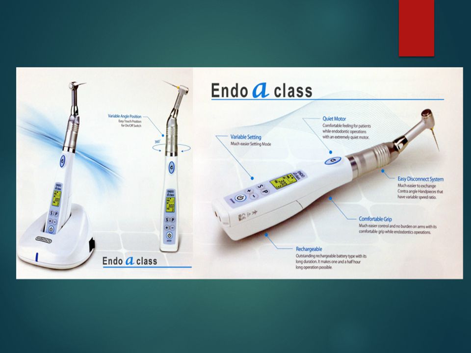
Rotary contra-angle handpiece in Endodontics
Medidenta/ micromega MM324 reduction gear handpiece Aseptico electric motor handpiece The Quantec ETM electric torque control motor Myco/union broach sprint EDM electronic digital handpiece Speed vary from 300 rpm to 2000o rpm

103
Rotary Niti instruments speed
Speed of the instruments Advantages Light speed RPM Remain central in canal minimum transportaion ,elbow formation Profile ISO sized instruments RPM Preservation natural canal path cutting effectiveness, tapered preparation Protaper 300RPM Superior flexiblity Hero 642 RPM Doesn’t create blockage RaCe RPM Used for both step back and step down Useful in calcified and narrow canal

104
Morita trio Auto –ZX cordless , battery powered endodontic , slow speed handpiece with a built in apex locator . Three automatic function starts automatically when the file enters the canal and stops when the file removed . If too much pressure is applied the handpiece stops automatically and reverses the rotation It also stops and reverses rotation when the file reaches the apical stop ,which determined by the built in apex locator.

105
Reciprocating handpiece
Accepts only latch type of instruments The quarter turn motion deliveres 3,000 times per minute Kerr , M4 handpiece which has 30 degree reciprocating motion Endo gripper handpiece has 10:1 gear ratio and a 45 degree turning motion.

106
Ultra sonic handpiece a system has an energy source 20 to 25 KH .it activates endodontic file, resulting in three dimensional activation of the file in the surrounding medium .

107
Attached to the dental unit. Powered by electricity.
Design of ultrasonic handpiece Attached to the dental unit. Powered by electricity. Primarily used for prophylaxis appointments. Attachments are similar in appearance to scaling instruments. Delivers a pulsating spray of water.

108
Uses of the Ultrasonic Handpiece
Remove calculus Remove stain Remove bonding materials from tooth surface after orthodontic appliances are removed Remove cement after orthodontic bands are removed

109
Sonic handpiece The sonic handpiece available today is micro mega 1500 or 1400 sonic air endo system The air pressure may be varied with an adjustable ring on the handpiece to give an oscillatory range of 1500 to 3000 cycles per second .

110
CONCLUSION The extensive knowledge of the different types of hand piece available, acurate speed, safety precautions, proper sterilization technique are essential for a dentist to do his work successfully.

111
References Operative dentistry-Sturdevant 4th edition
Operative dentistry-Charbenau 3rd edition Operative dentistry-Marzouk Operative dentistry-Vimal k.Sikri Practical Guide to technology in dentistry-Nicolas Pickards manual of operative dentistry-E.A.M Kidd & Smith

112
THANK YOU

Similar presentations


. All rights reserved. Chapter 35 Dental Handpieces and Accessories Copyright 2003, Elsevier Science (USA) All rights.>")


