Download presentation
Presentation is loading. Please wait.

1
WING SUPPORT CONCEPTS FOR WINGS # 2,3,6,7 AND 9 GARY MCGINNIS 09/19/2007 1 – TAPPING HOLES FOR STUDS 2 – STUD AND INSERT WELDING 3 – WELDING BRACKETS

2
1 TAPPING WINGS CONCEPT Wings and adjacent coil require drilling and tapping

3
STUD WOULD BE THREADED INTO LOWER COIL THREADED INSERT WOULD BE TIGHTENED PROVIDING COMPRESSIVE SUPPORT HEX NUT WOULD RETAIN WING FROM FLEXING OUTWARD C-B WING # 6 SHOWN INSULATING WASHERS AND SLEEVE (If Req’d)
")
4
A-B WING # 3 CAN BE BOLTED IN SIMILAR FASHON.

5
B-A WING # 2 CAN BE BOLTED IN SIMILAR FASHON.

6
B-C WING # 7 CAN BE BOLTED FROM INSIDE OR OUTSIDE. OUTSIDE PROVIDES BEST POSITION. 3” approx

7
Section thru C-C WING # 9 Only access from inside is thru the VV and thru port 17&18 Access from outside not possible due to flanges

8
20” If access were available WING # 9 could be bolted from inside or possibly welded depending on available room.

9
This is the area we need access to either bolt or weld C-C wing If this port were moved away from opening we would have access from inside the VV This view is cut thru the VV looking at port 17&18.

10
There appears to be room to slide this cover over to allow a person to get to the wing area. Again this is the area we need to get to A outside VV view with some coils removed

11
SUMMARY Wings require drilling, tapping and spotfacing for each bolt needed. The coil being bolted to will require drilling and tapping aligned with wing. Various lengths of shafts and plugs may be required to accommodate different wall and gap thicknesses. All wings have access and areas for multiple bolts if necessary. Bolt size TBD (3 / 4” shown in this example)
.")
12
2 STUD AND INSERT WELDING CONCEPTS WING WOULD BE BORED AND SPOTFACED. WELDING ON LOWER COIL. NO TAPPING OF WINGS OR COILS

13
CONCEPT USING THREADED INSERTS AND FABRICATED HEX BOLT FOR SCALE REFERENCE THIS BOLT IS 3 / 4” HEX IS 3-1 / 4” B-A WING # 2 SHOWN. OTHERS CAN BE MOUNTED SIMILAR

14
POSITION THREADED INSERT, FLANGED INSERT, AND INSULATING WASHER INTO HOLE ON WING BEFORE SETTING UPPER COIL IN PLACE. WELD INSERT TO LOWER COIL FROM INSIDE - INSERT IS Ø 1-1 / 2” OPTION TO PLUG WELD INSERT TO COIL.5” 1.2”

15
USING FLATS ON INSERT TIGHTEN WASHER AGAINST UNDERSIDE OF WING THIS PROVIDES SUPPORT FOR COMPRESSIVE WING MOVEMENT

16
INSTALL SPACER WASHERS AND FABRICATED HEX NUT THIS PROVIDES SUPPORT FROM WING DEFLECTING OUTWARD

17
CONCEPT USING WELDED STUD AND INSULATING BLOCK BETWEEN WING AND COIL A-B WING # 3 SHOWN. OTHERS CAN BE MOUNTED SIMILAR

18
INSTALL INSULATING BLOCK/WASHER PRIOR TO SETTING UPPER COIL IN PLACE WELD STUD THRU HOLE/SPOTFACE IN WING

19
ADD INSLUATING SLEEVE AND WASHERS AND TIGHTEN WITH FLANGE NUT

20
SUMMARY Wings require boring and spotfacing (No tapping req’d of coils). Welding of stud or insert must be done with upper coil in place. Only option to disassemble is to remove weld or break stud. Stud weld equipment available will determine hole sizes and have impact on bolts / inserts. It will need to be determined if coil casting surfaces will accommodate insulating block without additional grinding. (stud version) This concept for wing # 9 (C-C coil) possible with access from inside the VV.
 This concept for wing # 9 (C-C coil) possible with access from inside the VV..")
21
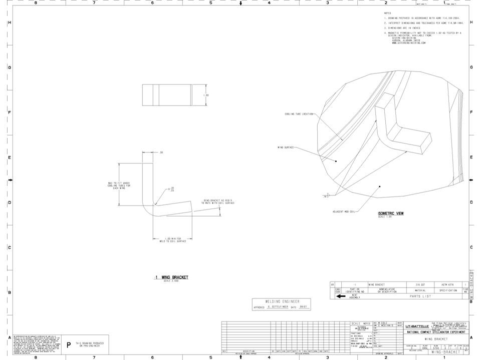
3 WELDING WINGS CONCEPT NO DRILLING OR TAPPING OF COILS OR WINGS

22
C-B WING #6BRACKET WELDED TO WING AND COIL OPTION TO USE WELD STUD AND NUT

23
B-A WING #2

24
A-B WING #3

25
B-C WING #7

27
SUMMARY Brackets to be bent from approx 1 / 2” x 1” bar stock, length and bend as req’d. Most wing areas provide space for multiple brackets if req’d for strength. If electrical isolation is req’d weld studs with insulating washers/sleeves and hex nuts could be used. Welding for wing #9 possible if access is available thru the VV ports 17&18. Only other option available, to date, for #9 is using current design wing bladder.

Similar presentations


>")

 was introduced in 2011. Parts do not.>")


